Partitions are part of the wall located between various openings located on the same level. For example, such a structure can separate windows or doors.
The very configuration of the piers allows us to speak about their significant vulnerability and fragility, in general design walls are the most loaded areas. It's not surprising that repair work we have to resort to strengthening them quite often.


Strengthening piers with reinforcement mesh
The most obvious indication for the use of this reinforcing structure is clearly visible cracks formed in the masonry.
In this case, it is necessary to construct special wire clips with a cross-section of no more than 5 mm. The reinforcing mesh is welded in such a way that a closed loop is formed. The resulting structure is tightly applied to the wall and secured to it with pins (nails) 100-150 mm long. Nails must be driven into the seams of the reinforced brickwork. The final stage– covering the working area with shotcrete concrete. Plaster will also work. But in any case, the layer of material should be no thinner than 20 mm.
Strengthening the walls with a steel clip
First you need to assemble the steel cage. To do this, you will need longitudinal corners measuring 50x50 mm. Steel strips (strips) measuring the same 50x5 mm are welded to them at a distance of no more than 500 mm from each other.
To create the best technological characteristics of the manufactured holder and for its strongest adhesion to the reinforced masonry, you can resort to a little professional trick - heat the strips to 150-200°C before welding.
The resulting clips should be laid on the surface of the wall, which must first be plastered and leveled.


Strengthening piers with reinforced concrete clips
This technique is used if the masonry being reinforced has complex configuration and in cases of serious damage to the surface of the wall.
To make a reinforced concrete frame, it is best to use concrete of class B15-B20. The reinforcing structure must be reinforced with a spatial frame with longitudinal and transverse rods.
If you are dealing with a wall of considerable length (2 or more times the thickness), you need to provide for installation additional connections, which will be passed through the reinforced pier.
Tkachev Sergey
Inspection of stone and reinforced concrete stone structures is carried out taking into account the requirements of SNiP 11-22-81 “Stone and reinforced stone structures”, as well as “Recommendations for strengthening stone structures of buildings and structures”.
Before the examination stone structures it is necessary to identify their structure by highlighting the load-bearing elements. It is especially important to take into account the actual dimensions of the load-bearing elements, design scheme, assess the magnitude of deformations and destruction, identify the conditions for supporting beams, slabs and other bendable elements on the masonry structure, the condition of the reinforcement (in reinforced masonry structures) and embedded parts. The size and nature of defects and the presence of typical damage (chips and cracks) directly depend on the above conditions.
For strength determination masonry use tools and instruments mechanical action, as well as ultrasonic devices. Using hammers and chisels through a series of blows, you can approximately assess the qualitative condition of the stone and concrete structures. More accurate data is obtained using special hammers, i.e. mechanical devices based on the assessment of traces or results of impacts on the surface of the structure being tested. The simplest, although less accurate, tool of this type is the Fizdel hammer. A ball of a certain size is pressed into the striking end of the hammer. By means of an elbow strike, creating approximately the same force different people, a trace-hole remains on the surface under study. According to the size of its diameter c. Using a calibration table, the strength of the material is assessed .
A more accurate tool is the Kashkarov hammer, when using which the force of the ball hitting the material under study is taken into account by the size of the mark on a special rod located behind the ball.
But the most modern and accurate mechanical devices are spring ones: the Academy device Utilities RSFSR, Central Research Institute building structures. The operating principle of these devices is based on taking into account a certain impact force caused by the release of a charged spring. A device of this type is a housing in which a spiral spring is placed, connected to a hammer rod. After pressing the trigger, the spring is released and the firing pin strikes. In the TsNIISK device, the impact force can be set to 12.5 or 50 kg/cm 2 For stone materials of varying strength.
To determine the bends and deformations of vertical surfaces, their shape and the nature of deviations from verticality and plane, use a level with a special attachment that allows sighting, starting from 0.5 m instead of the minimum 3.5 m when there is no nozzle.
The relief of vertical surfaces is revealed by the method of sighting the instrument from one of its positions on the rail, applied horizontally to pre-designated points of the surface being examined. The results of measuring deformations of horizontal or vertical surfaces are plotted on diagrams on which, for clarity, lines of equal deviations from the horizontal or vertical are revealed, like horizontals planes. The cross-section is given equal to 2-5 mm depending on the degree of deviation or violation of the position or local defects of the element being examined and its overall dimensions.
However, first of all, it is necessary to find out the nature of the negative changes in the masonry and determine whether the process of crack formation has stabilized, or whether their number and opening width are increasing over time. For this purpose, they are installed in the masonry itself beacons. The beacon is a strip of plaster, glass or metal that covers both sides of the crack. Lighthouses made of plaster and glass will burst if the deformation that caused the cracks continues.
| Instruments for diagnosing the strength of a material: a - Fizdel hammer; b something Kashkarova; c - TsNIISK pistol: 1 - calibrated ball; 2 - angular scale; 3 -
calibration table; 4-replaceable rod for fixing the impact mark |
|
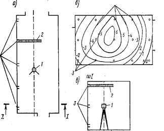 |
Measuring vertical surface deformations using a level with an optical attachment: a-plan; b- wall surface; c - section; 1 - level; 2 - rail; 3 - places where the slats are applied; 4 - lines of equal deviations from the plane |
 |
Beacons for monitoring the condition of cracks: /-crack; 2-plaster and alabaster mortar; 3- wall material; 4- plaster beacon; 5 - glass lighthouse; 6 - metal plate; 7 - marks every 2-3 mm; 8 - nail |
By measuring the magnitude of the divergence of the halves of the beacon, the nature of the change in the crack or its stabilization is determined. A metal beacon is attached to one side of the crack, and it can move along its other edge, along the other side of it, where the initial and subsequent positions of the end of the beacon are recorded. The simplest beacon is paper beacon, which is a strip of paper glued to a crack; with further expansion of the crack, the paper beacon breaks.
Cracks in load-bearing masonry structures correspond to the stages of crack formation (or stages of masonry operation under compression). With efforts in masonry F
, not exceeding the effort Fcrc
when cracks appear in the masonry, the structure is sufficient to withstand the existing load bearing capacity, cracks do not form. Under loads F  Fcrc
the process of crack formation begins. Since masonry does not resist tension well, there are cracks on stretched surfaces (areas)
Fcrc
the process of crack formation begins. Since masonry does not resist tension well, there are cracks on stretched surfaces (areas)
appear much earlier than the possible destruction of the structure.
The main reasons for the formation of cracks are:
1) poor quality of masonry (poor mortar joints, non-compliance with dressings, backfilling in violation of technology, etc.);
2) insufficient strength of the brick and mortar (cracks and curvilinearity of the brick, non-compliance with the drying technology during its manufacture; high mobility of the mortar, etc.);
3) the combined use in masonry of stone materials of different strength and deformability (for example, clay bricks together with silicate bricks or cinder blocks);
4) use of stone materials for purposes other than their intended purpose (for example, sand-lime brick in conditions of high humidity);
5) low quality of work performed in winter time(use of bricks that have not been cleared of ice; use of frozen mortar, absence of anti-frost additives in the solution);
6) failure to perform temperature-shrinkage seams or unacceptable long distance between them;
7) aggressive influences external environment(acid, alkaline salt effects; alternate freezing and thawing, moistening and drying);
8) uneven settlement of the foundation in the building.
It is no coincidence that the foundation settlements are indicated last condition for the occurrence of cracks in masonry. It should be borne in mind that during the period of mass construction in masonry, mortars without antifreeze additives were used, thin, non-plastic, i.e. very cheap. All this contributed to abundant education shrinkage
cracks that must be separated from the clean surface during examination sedimentary
cracks that have a specific, easily identifiable character.
Let's consider the process of crack formation in masonry during compression
First stage- the appearance of the first hair cracks in individual stones. An effort Fcrc
at which cracks appear at this stage depends mainly on the type of mortar used in the masonry:
- in masonry with cement mortar F crc = (0.8 - 0.6) F u ; ;
- in masonry with complex mortar F crc = (0.7 - 0.5) F u ;
- in masonry on lime mortar F crc = (0.6 - 0.4) F u ,
Where F u—
destructive force.
Second stage— germination and unification of individual cracks. This stage begins and proceeds more intensely along the southern facade of the building, which experiences the greatest temperature fluctuations in the atmospheric environment. In addition, the growth of cracks is observed when external drains are improperly organized or their system is disrupted in places where the masonry periodically gets wet.
Third stage– further formation of large surfaces of destruction and exhaustion of the strength of the masonry.
 |
 |
|
The photograph shows a structure with an attic resting on an internal transverse wall. On the free part of the roof, a slope was created for an organized external drainage system, but the corner of the building was significantly wetted. The arrow points to a developing crack that appeared after one year of operation of the reconstructed structure. |
Defects in brickwork and their causes: a-wear from 20 to 40%; b-wear 41-60%; c- overloaded walls with wear up to 40%; d - the same, with greater wear; d - exposure of brickwork due to wear of plaster |
When analyzing the pattern of cracks, it should be remembered that the appearance of individual cracks in the dressing stones indicates overstress in the masonry. Crack development in the second stage indicates significant overstressing of the masonry and the need to unload or strengthen it.
When large destruction surfaces form, it is advisable to replace the masonry with a new one or strengthen it with a structure that can fully withstand the operational load.
During the operation of the structure, cracks may open due to illegal long length temperature block or due to the absence of a temperature-shrink seam at all. During the period of reconstruction with the construction of bay windows, hanging elevators, installing additional and attic floors Cracks may appear in the masonry due to the insufficient area of support of the lintels on the wall and the low strength of the masonry, from overloading the pier and the low strength of the masonry. There are other possible causes of cracking. For example, chaotically located cracks often occur in structures that are in close proximity to the place where piles are driven, or in old buildings, the wear of the brickwork reaches 40% or more.
Strength bricks and stones must be determined in accordance with the requirements of GOST 8462-85, solution— GOST 5802-86 or SN 290-74. Density and humidity masonry determined in accordance with GOST 6427-75, 12730.2-78 by establishing the difference in the weight of the samples before and after drying. The frost resistance of stone materials and mortars, as well as their water absorption, is established according to GOST 7025-78.
Samples for testing are selected from lightly loaded structural elements, provided that the materials used in these areas are identical. Samples of bricks or stones must be intact without cracks. From stones irregular shape cut cubes with edge sizes from 40 to 200 mm or drill out the cylinders (cores) diameter from 40 to 150 mm. To test solutions, cubes with edges from 20 to 40 are made mm, composed of two mortar plates glued together with gypsum mortar. Samples are tested for compression using standard laboratory equipment. Areas of brick (stone) from which samples were taken for testing must be completely restored to ensure the original structure.
Technology for restoring and strengthening brickwork
As noted above, the brick buildings of mass-produced residential buildings had high reliability and a significant margin of safety. But long term exploitation, violation technical specifications contents could cause significant damage to load-bearing brick walls. Depending on the visible damage and condition of the structures, the loads acting on them, and other factors that impede normal operation, during reconstruction measures are taken to restoration load-bearing capacity of brickwork. In addition, when increasing the number of floors of a structure or otherwise increasing the construction volume of a structure, the need arises for strengthening brick structures.
Recoverybearing capacity of masonry comes down to sealing and localizing cracks. Naturally, this problem must be solved after identifying and eliminating reasons that caused cracking:
1) eliminate or stabilize uneven foundation settlements by strengthening foundations or foundations;
2) change the conditions for transferring the load to the cracked pier in order to redistribute the load over a larger area;
3) redistribute the loads to other (or even additional) structures in case of insufficient strength of the masonry itself.
It should be noted that sealing cracks should also accompany measures to strengthening brick structures, which are necessary when loads increase and it is impossible to redistribute them to other elements of the structure.
Technologically, sealing cracks in brick walls can be done using one of the following methods or a combination of them.
Injection of cracks - injection of solutions of liquid cement or polymer-cement mortar, bitumen, resin into cracks in damaged masonry. This method of restoring the load-bearing capacity of masonry is used depending on the type of structure, the nature of its further use, the available injection capabilities, and most importantly, if the crack is local and has a small opening. It can be done using various materials. Depending on their type they distinguish silicization, bituminization, smolization And cementation. Injection allows not only to monolith the masonry, but also to restore and, in some cases, increase its load-bearing capacity, which occurs without increasing the transverse dimensions of the structure.
The most widely used are cement and polymer-cement mortars. To ensure injection efficiency, Portland cement grade of at least 400 with a grinding fineness of at least 2400 is used. cm 2 /g, with a cement paste density of 22 - 25%, as well as Portland slag cement grade 400 with low viscosity in liquefied solutions. Sand for the solution is used fine with a fineness modulus of 1.0 - 1.5 or finely ground with a grinding fineness of 2000-2200 cm 2 /g. To increase the plasticity of the composition, plasticizing additives in the form of sodium nitrite (5% by weight of cement), polyvinyl acetate PVA emulsion with a polymer cement ratio P/C = 0.6 or a naphthalene-formaldehyde additive in the amount of 0.1% by weight of cement are added to the solution. .
Quite stringent requirements are imposed on injection solutions: low water separation, required viscosity, required compressive and adhesive strength, low shrinkage, high frost resistance.
At small cracks in a clutch (up to 1, 5 mm) use polymer solutions based on epoxy resin(epoxy ED-20
(or ED-16) - 100 wt.h.; modifier MGF-9 — 30 wt.h.; hardener PEPA – 15 parts by weight; finely ground sand - 50 wt.h), as well as cement-sand mortars with the addition of finely ground sand (cement - 1 parts by weight; superplasticizer naphthalene-formaldehyde – 0.1 parts by weight; sand - 0.25 parts by weight; water-cement ratio – 0.6).
At more significant opening of cracks use cement-polymer solutions of composition 1:0.15:0.3 (cement; PVA polymer; sand) or 1:0.05:0.3 (cement: plasticizer sodium nitrite: sand), W/C = 0.6 , sand fineness modulus M k =1. The solution is injected under pressure up to 0.6 MPa. The density of crack filling is determined 28 days after injection.
The solution is injected through injectors with a diameter of 20-25 mm. They are installed in special drilled holes after 0.8-1.5 meters along the length of the crack. The diameter of the holes should ensure installation of the injector tube on the cement mortar. Hole depth – no more 100 mm, the injector tube is fixed in the hole with caulked tow.
 Injection of cracks up to 10 mm wide cement-sand mortar:
1- masonry; 2- crack; 3- holes for injectors every 800-1500 mm; 4- steel injector tube; 5- tow, caulked with glue; 6- solution supply
Installation of reinforcing steel brackets
used in methods for restoring the bearing capacity of masonry when cracks open more 10 mm. To do this, a recess is made in the masonry using a milling cutter to the size of the bracket. The bracket is secured with bolts along the edges, the crack itself is usually injected with cement-sand mortar and caulked with a rigid mortar.
Installation of brackets made of reinforcing steel: 1-reinforced wall; 2-crack in the wall, injected with cement-sand mortar after installing brackets; 3-brackets made of reinforcing steel; 4-groove in the masonry, selected with a milling cutter; 5-recesses at the ends of the groove, made with a drill; 6-filling grooves and recesses with cement-sand mortar
At significant damage masonry a network of cracks staples perform double-sided, in this case the masonry experiences double-sided compression. Development of numerous end-to-end cracks can be stopped by using a staple instead strip steel plates , which are installed in increments of 1.5-2 wall thicknesses.
|
|
|
|
|
|
|
|
|
Double-sided brackets made of reinforcing steel with bolts: 1- masonry; 2- through crack; 3- plates made of strip steel; 4- coupling bolts; 5 holes in the wall |
||


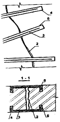
The damage can be so significant that in some cases partial dismantling and re-building of the destroyed brickwork is required. Typically this is done with the device inserts of brick locks equipped with an anchor .
 |
Wide, more 10 mm, crack ( 1 ) intercepted by a one- or two-sided overlay ( 2) , no longer made of strip steel, but of rolled metal, which is attached to the wall with anchor bolts. In this case, the overlay is called anchor. Along the entire length of the development of the crack, the damaged brick is removed to a thickness of two bricks and replaced with reinforced masonry on cement-sand mortar, called brick castle (3-4
).
|
 |
Partial or complete filling of openings with masonry: 1- reinforced partition; 2- window openings; 3- reinforced brickwork of grade M75-100 on mortar M50-75; 4- seam, wedged with a metal plate and caulked with cement-sand mortar |
 |
Unloading scheme brick walls: 1 - jumpers /chka-, 2 - boards 50-60 mm; 3- racks with a diameter of more than 20 cm; 4 - wooden wedges; 5- temporary fastening of racks |
Increased bearing capacity and stability of piers can be ensured increasing cross-sectional area
, device of various clips
or metal frame.
Increasing cross-sectional area The wall is reached by increasing its width. In this case, new sections of masonry are laid out on both sides of the wall, which is securely tied to the old one, and, if necessary, reinforced. Damaged load-bearing walls are unloaded, the cross-sectional area of the walls increases, and the area decreases accordingly window openings, That's why window blocks subject to replacement.
When leaning on a reinforced wall truss structure or the wall deviates from the vertical by more than 1/3 of the thickness of the brick, the wall is first unloaded by placing temporary wooden or metal pillars on gypsum mortars.
Main ways reinforcement of brickwork,
are well-tested methods of device clips, build-ups
or shirts,
divided into reinforced concrete
And mortar
. When amplified reinforced concrete frames, jackets And build-ups class B10 concrete and class A1 reinforcement are used, the transverse reinforcement spacing is taken to be no more than 15 cm. The thickness of the holder is determined by calculation and varies from 4
before 12 cm.
Mortar clips, shirts And building up, also called plastering, differ from reinforced concrete because they use grade 75-100 cement mortar, which protects the reinforcement reinforcement.
Device reinforced concrete frame effective in case of surface destruction of the material of piers and pillars to a small depth or when deep cracks occur, when widening of the piers is possible. In the first case, the destroyed sections of the pier are cleared to a depth of at least the thickness of the reinforced concrete casing, and the section of the pier does not change as a result of its construction. In the second case, the cross-section of the pier is increased due to the installation of a reinforced concrete cage.
The technological process of installing a reinforced concrete frame of piers consists of removing window fillings, clearing damaged areas or cutting down the pier to the required depth, removing window quarters, installing reinforcement, installing formwork, concreting, maintaining concrete, removing formwork and dismantling scaffolding. The working reinforcement of a reinforced concrete cage can be pre-stressed by heating up to 100-150° C (for example, heating by electric current).
 |
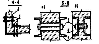
Construction of reinforced concrete frames: a-without increasing the cross-section of the pier; b-with magnification sections pier |
 |
|
 |
Construction of a pre-stressed plaster frame: 1-reinforced wall; 2-metal plates with holes for cords; 3-strand-connections; 4 holes in the wall for cords; 5-reinforcing bars welded to the plates and tightened in pairs; 6- plaster made of cement-sand mortar; 7-reinforcement mesh tied to bars |
Instead of reinforcement cages when reinforcing, it is possible to use wire mesh with a diameter 4-6 mm with cell 150x150 mm. In both cases of reinforcement, both meshes and frames are attached to the reinforced surface with pins (anchors).
For large areas, additional tie clamps are installed in steps of no more than 1m at medium length75 cm.
The formwork of the reinforced concrete frame is built up from the bottom up during the concreting process. To construct reinforced concrete frames, the shotcrete method is used, in which formwork is not required. In this case, it is applied under pressure to the reinforced surface of the wall. concrete mixture using a cement gun. The advantage of this method of constructing a reinforced concrete frame is the mechanization of the concreting process. The reinforced concrete cage increases the load-bearing capacity of the element enclosed in it by 2 times
 |
|
|
Reinforced concrete frame clamps: 1- reinforced wall surface; 2- fittings with a diameter of 10 mm; 3- tie clamps with a diameter of 10 mm; 4 - holes in the masonry; 5 - concrete frame; 6- reinforcement cages |
|
 |
 |
| Construction of a plaster or reinforced concrete jacket: 1-reinforced wall; 2-armholes; 3-plaster jacket 30-40 mm or reinforced concrete jacket 60-100 mm thick; 4-reinforcement with a diameter of 10 mm; 5-reinforcement with a diameter of 12 mm; 6-metal pins | Construction of a reinforced concrete core: 1-reinforced wall; 2-openings; 3-post (core) made of reinforced concrete;
4-niche cut into the pier; 5-reinforcement frame; 6-concrete |
Mortar shirts and extensions
differ from clips only in one design feature - they are made one-sided. The shirt can be made not over the entire width of the wall - in the form core.
Sometimes steel frames for reinforcing brickwork on constantly used buildings are left without a protective coating with mortar or concrete, creating metal carcass
gain.
 |
 |
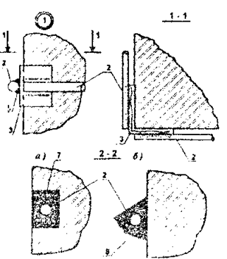
| Reinforcement of piers with a metal frame: a- narrow pier; b- wide pier; 1-brick element; 2-steel corners; 3-bar; 4-cross link |
|
 |
Construction of overhead belts from corners: 1-reinforced partition; 2-corners of overhead belts; 3-cross bars; 4-pin bolts; 5-plaster with cement-sand mortar on a metal mesh |
The construction of a metal frame of piers is less labor-intensive and material-intensive than the construction of a reinforced concrete frame, and is widely used.
Preparation for the installation of metal frames of piers consists of unloading the piers, removing the filling of window openings and cutting down the quarters. With this method, corner steel racks are installed at the corners of the piers to their full height and tightly adjusted to the piers, which are connected after 30-50 cm in height with strip steel, butt-welded to the corner flanges. Then the wall is covered with wire metal mesh and plastered.
The metal frame can be placed on the wall or embedded flush into it. In the second case, before installing the frame, the corners of the walls are cut off and horizontal grooves are punched in the places where the metal connecting strips are installed.
After installing the frame, the gaps between metal elements and the wall is carefully caulked with mortar. If the lintels resting on the pier are also destroyed, it becomes more effective to strengthen the pier by adding racks from the corners. In this case, the racks are made slightly longer than the distance between the lintel and the floor. At the top they are attached to the exposed reinforcement of the jumpers, and at the bottom to an overhead belt made of channel, mounted on the body of the object being reconstructed. The racks are straightened in pairs with clamps, thus creating pre-stress. Straightening, breaks, cuts in the flanges of the corners are welded.
Gain corners buildings are also advisable to produce using channel overlays length 1.5-3 m. Overlays can be placed both on the outside and on the outside inner surface walls. They are connected to the brickwork using tie bolts installed in pre-drilled holes. The coupling bolts are located along the height of the reinforced part of the masonry through 0.8-1.5 m.
|
|
Connecting the racks from the corners: 1-reinforced partition; 2-openings; 3-racks of unequal corners, curved to the side; 4-break lines; 5-fold part; 6-exposed reinforcement; 7-welding; 8-solution |
|
|
|


If local deformations occur and to prevent further crack opening, it is carried out by strengthening interface zones longitudinal and cross walls building unloading beams . Unloading beams are installed in previously punched grooves on one or both sides of the wall at the level of the top of the foundation or lintels of the first floor.
Double-sided beams through 2-2.5 m connected by bolts with diameter l6-20 mm, passed through previously drilled holes in the beams and wall. One-sided beams are installed on anchor bolts, the smooth ends of which are secured in the wall by installing them with cement mortar into previously drilled sockets. Beam connections with bolts are secured with nuts. Anchor bolt spacing 2-2.5 m.
The gaps between the beam flanges and the brickwork are carefully caulked cement mortar composition 1:3. For the manufacture of unloading beams, a channel or I-beam No. 20-27 is used. In places where walls break, cracks are installed on each floor using clamps made from scraps of rolled stock with a length of at least 2 m. Before installing the bracket-screed, a groove is cut out in the wall so that the screed is installed flush with the surface brick wall. Holes for bolts are drilled in the wall and in the screed according to the markings. 20- 22 mm, with the help of which the bracket-screed is attached to the wall. The distance from the crack to the bolt installation site must be at least 70 cm. Before installation, the tie-brace is wrapped wire mesh or wire 1-2 mm. After installing the structure, the crack and the fine are carefully sealed with a brand solution M100.
 |
 |
|
Installation of metal plates (frame) when reinforcing a building: 1-deformed building; 2-cracks in the walls of the building; 3-linings made of channels or metal plates; 5-pin bolts; 6-fine for installing plates, sealed with mortar; 7-holes in the walls for bolts, after installing the bolts they are caulked with mortar |
Typically, development cracks related to uneven settlement of foundations, requires additional measures not only to increase the load-bearing capacity of the masonry, but the rigidity of the entire structure as a whole. Gross violations of masonry technology, unacceptable operating conditions of the structure, as in the case of uneven settlement of foundations, cause not only the development of cracks in window and doorways, but also violations of the verticality of enclosing structures.
In places tearing off external walls from internal ones to restore the rigidity of the building, connections are made from metal frames or reinforced concrete dowels. In this case they say that the building reinforced.
However, most often, after eliminating the causes of uneven settlement of the foundation, the building needs tightening the body generally. Perhaps, the only way such contraction is creation of tension belts .
 |
 |
 |
 |
Construction of external stressed belts: 1-deformed building; 2-steel rods; 3-roll profile from angle No. 150; 4 turnbuckles; 5-weld seam; 6- cracks in the walls of the building; 7-hole in the wall filled with cement-sand mortar
It should be emphasized here that the most common mistake in strengthening the body brick buildings with a hard design diagram is the creation vertical stiffening discs(laying in or reducing the area of window openings, installing vertical metal frames, etc.), while the most important thing here is horizontal stiffening disc. The tension belt, also called "bandage", is made from reinforcing bars with a diameter 20-40 mm connected by turnbuckles.
In rare cases, rolled steel is used instead of reinforcement. The result is a reinforcing element that absorbs both tensile and compressive forces, called spacer connection. Spacer ties are installed at the level of the covering and at the level of interfloor ceilings; they can be located both from the outside and from the outside. inside structures.
 |
 |
 |
|
| Construction of internal stress zones: 1-deformation building; 2-steel rods with nuts; 3-metal plates; 4 turnbuckles; 5-holes in the walls, which are sealed with mortar after packing the strands; 6-cracks in the walls of the building | |
Strengthening interfloor ceilings residential buildings series 1-447 is determined by the presence of short cracks and fragmentation brick stone in places where floor slabs support. The main cause of destruction is usually an insufficient support area for the floor slab or the absence of a distribution pad.
Most effective technique amplification is a mounting technology steel rods And spacer ties under the floor slab, since, as already noted, the creation of a horizontal rigidity disk in buildings of this type is of paramount importance. However, this is a very expensive and time-consuming method; it is only possible with complete reconstruction with resettlement of residents. Therefore, they try to fulfill local strengthening damaged structures.
Local reinforcement, depending on the type of floor slabs, during partial or phased reconstruction is carried out by:
—increasing the support area of the beam using metal or reinforced concrete racks, the force from which is transmitted outside the destruction zone;
-increasing the support area of the slab by means of a belt fixed in the zone of destruction of the masonry;
- devices under the end of the floor slabs of reinforced concrete pads.
Calculation of brick elements reinforced with reinforcement and clips
Longitudinal reinforcement , designed to absorb tensile forces in eccentrically compressed elements (at large eccentricities), in bending and tensile elements, in reinforcing brickwork during reconstruction, is quite rare, therefore in this section not considered. However, with the growth seismic dangers of some areas central Russia due to underground workings and other anthropogenic factors, as well as when laying railways and highways near residential areas, longitudinal reinforcement is used when lining thin (up to 51 cm) brick walls of reconstructed buildings.
Mesh reinforcement masonry sections significantly increases the load-bearing capacity of reinforced elements of stone structures (pillars, piers and individual sections of walls). The effectiveness of mesh reinforcement during reinforcement is determined by the fact that reinforcing meshes laid in the horizontal seams of masonry sections prevent its transverse expansion during longitudinal deformations, caused acting loads, and thereby increase the load-bearing capacity of the masonry body as a whole.
Mesh reinforcement is used to strengthen masonry made of all types of bricks, as well as ceramic stones with slot-like vertical voids with a row height of no more than 150 mm. Reinforcement of concrete and masonry with mesh reinforcement natural stones with a row height of more than 150 mm little effective.
For masonry with mesh reinforcement, mortars of grade 50 and higher are used. Mesh reinforcement is used only for flexibility or, as well as for eccentricities located within the core of the section (for rectangular sections e 0<0,33 y). При больших значениях гибкостей и эксцентрицитетов сетчатое армирование не повышает прочности кладки.
For example, it is required to determine the cross-section of longitudinal reinforcement for a brick pillar 51 x 64 cm, height 4.5 m. The pillar is made of ordinary clay bricks of plastic pressing brand 100
on brand solution 50
. In the middle section of the column, the reduced calculated longitudinal force acts N p=25 t, applied with eccentricity e o =
25 cm towards the side of the section having size 64 cm.
We reinforce the column with longitudinal reinforcement located in the tension zone outside the masonry. We reinforce the compressed zone of the cross section of the column structurally, since when the reinforcement is located externally, frequent installation of clamps will be required to prevent buckling of the compressed reinforcement, which will require additional waste of steel. The installation of structural reinforcement in the compressed area is mandatory, as it is necessary for attaching the clamps.
Cross-sectional area of the pillar F=51 x 64 = 3260 cm 2. R=l5 kgf/cm 2(at F > 0.3 m 2). Design resistance of longitudinal reinforcement made of steel class A-1R a =l900 kgf/cm2.
We take stretched reinforcement from four rods with a diameter of 10 mm F a =3.14 cm 2.
Determine the height of the compressed section zone X at h 0 =65 cm, e=58 mass media b=51 cm:
1.25-15-51 x (58-65+)-1900 -3.14-58 = 0,
and from the received quadratic equation define x= 35 cm<
0.55h o =36 cm.
Since the condition is satisfied, the load-bearing capacity of the section is determined by at =1000:
pr = = =7
hence = 0.94.
Section bearing capacity
0.94(1.25 x 15 x 51 x 35-1900 x 3.14) =25.6 t >N p =25 t.
Thus, with the adopted reinforcement cross-section, the bearing capacity of the column is sufficient.
Complex structures are made of masonry reinforced with reinforced concrete, working together with the masonry. It is recommended to place reinforced concrete with outside masonry , which allows you to check the quality of the laid concrete, the grade of which should be taken to be 100-150.
Complex structures are used in the same cases as masonry with longitudinal reinforcement. In addition, it is advisable to use them, just like mesh reinforcement, to strengthen heavily loaded elements under axial or eccentric compression with small eccentricities. The use of complex structures in this case makes it possible to sharply reduce the cross-sectional dimensions of walls and pillars.
Elements reinforced with clips are used to strengthen pillars and piers that have a square or rectangular cross section with an aspect ratio of no more than 2.5. The need for such reinforcement arises, for example, when adding to existing buildings. Sometimes it is necessary to strengthen masonry that has cracks or other defects (insufficient strength of the materials used, poor quality of masonry, physical deterioration and so on.)
Clips, as well as mesh reinforcement, reduce transverse deformations masonry and thereby increase its load-bearing capacity. In addition, the clip itself also absorbs part of the load.
In the previous sections, three types of clips were considered: steel, reinforced concrete and reinforced plaster .
Calculation of elements made of brickwork, reinforced with clips, under central and eccentric compression at small eccentricities (not beyond the core of the section) is carried out according to the formulas:
with steel frame
N n [(m to R + ) F+R a F a ];
with reinforced concrete frame
N n [(m to R + ) F+m b R pr F b +R a F a ];
with reinforced plaster casing
N (m R + ) F.
The values of the coefficients are accepted:
at central compression=1 and =1;
with eccentric compression (by analogy with eccentrically compressed elements with mesh reinforcement)
1 — , where
N p - reduced longitudinal force; F- masonry cross-sectional area;
F a- cross-sectional area of the longitudinal corners of the steel cage installed on the mortar, or the longitudinal reinforcement of the reinforced concrete cage;
f b - cross-sectional area of the concrete cage enclosed between the clamps and the masonry (without taking into account the protective layer);
R a - design resistance of the transverse or longitudinal reinforcement of the cage;
- buckling coefficient, when determining the value A accepted as for unreinforced masonry;
t k - masonry operating conditions coefficient; for masonry without damage t to=1; for masonry with cracks t to =0,7;
t b - concrete operating conditions coefficient; when transferring the load to the holder from both sides (bottom and top) t b
=1; when transferring the load to the holder from one side (bottom or top) t b=0.7; without direct load transfer to the holder t b =0,35.
- percentage of reinforcement determined by the formula
x 100,
Where f x- cross-section of the clamp or crossbar;
h And b- dimensions of the sides of the reinforced element;
s- distance between the axes of the transverse bars with steel cages ( hs b, but no more than 50 cm.) or between clamps for reinforced concrete and reinforced plaster clamps (s15 cm).
For example, in the middle section of the pier measuring 51x90 cm, located on the ground floor of the building, after completion of construction of the superstructure, the calculated longitudinal force will apply N n =60 t applied with eccentricity e O = 5 cm, directed towards the inner edge of the wall. The partition is made of sand-lime brick, grade 125, with mortar, grade 25. The height of the wall (from the floor level to the bottom of the prefabricated reinforced concrete floor) is 5 m. It is necessary to check the load-bearing capacity of the wall.
Pier section F= 51 x 90 = 4590 cm 2 > 0.3 m 2.
Design resistance of masonry R = l4 kgf/cm 2. Distance from the center of gravity of the section to its edge in the direction of eccentricity
y = = 25.5 cm; = =0.2<0,33,
the eccentricity is within the core of the section. We design the wall for eccentric compression with low eccentricity. The elastic characteristics of sand-lime brick masonry on mortar grade 25 is = 750.
Reduced flexibility of the wall np == 11.3.
Buckling coefficient = 0.85.
Coefficient taking into account the influence of eccentricity = 0.83.
Let us determine the load-bearing capacity of the pier:
0.85 x 14 x 4590 x 0.83 = 45,200kgf
Since the load-bearing capacity of the wall turned out to be insufficient, we reinforce it with a frame made of steel isosceles angles measuring 60x60 mm, d=6 mm. The corners are installed on the mortar in the corners of the wall and connected to each other by strips of strip steel with a section of 5x35 mm, welded to the corners at a distance s=50 cm along the height of the wall.
Next, we determine the load-bearing capacity enhanced pier. Coefficient of masonry operating conditions t k =1. Design resistance of steel strips R a =1500 kgf/cm2. Sectional area of the plank f x= 0.5x3.5= 1.75 cm 2. Design resistance of the corners of the cage (the load is not transferred to the corners) R a =430 kgf/cm 2. Sectional area of corners F a=6.91x4=27.6 cm 2. Next, we determine the coefficients and , =0,83, =1-=0,61 and the corresponding percentage of reinforcement: =x100=0.21%
Hence the load-bearing capacity of the reinforced wall will be:
0.83.0.85[(14 +0.61хх)4590+430 x27.6]=63800kgf > N p =60000 kgf
The load-bearing capacity of the reinforced wall is sufficient. 
Load-bearing walls in buildings are used with frameless structural designs; they are the main vertical load-bearing elements and at the same time serve as enclosing structures, i.e. must have not only sufficient strength, stability and load-bearing capacity, but also the necessary thermal properties - ensure the specified temperature conditions in the premises, a standardized level of steam, air and sound impermeability.
Below are major defects and damage , which are encountered by the specialists of Engineering Center ExpertProject LLC during inspections, and also indicate measures to eliminate certain damages to bring the structure into compliance with the requirements of building codes.
1. Insufficient load-bearing capacity of wall sections (piers) to perceive the effect of actual operational loads or loads designed during the reconstruction of the building. This defect is determined only by the results of a calculated assessment based on the initial data identified during a field inspection. This defect is eliminated by strengthening the partitions and sections of walls with steel frames or reinforced concrete jackets.
2. Damage to wall material under the influence of external force or atmospheric factors are eliminated by repair methods: sealing cracks with injection mortar, monitoring cracks, re-lining individual damaged sections of walls.
3. Characteristic cracks in the walls with uneven settlements of foundations and foundations. Elimination of further development of these deformations is carried out by strengthening the foundation soils or strengthening the foundations, as well as increasing the spatial rigidity of the building through the installation of monolithic reinforced concrete belts, steel tension belts or the introduction of new walls and rigid structures.
4. Insufficient thermal, sound and vapor insulation qualities of the walls are eliminated by increasing and improving them.
Strengthening load-bearing walls with reinforced concrete or steel frames.
Steel clips, as a rule, are made from rolled angles, installing them in each corner of the pier section. Reinforcement angles are selected by calculation based on the wall overload. The steel corners of the clips are pulled together along the edges of the cross-section of the pier with steel strips, preheated to a temperature of 250-300 C. In the upper and lower parts, the steel clips are connected to the walls by distribution corners that ensure the transfer of forces. At the same time, based on the calculation estimate, it is necessary to maintain the load-bearing capacity of the masonry for pushing in the places where the distribution corners are installed.
For reinforcement with reinforced concrete jackets, frames made of round reinforcing steel with a diameter of 6mm - 12mm are used with a height spacing of clamps of no more than 150mm. The pitch of the vertical reinforcing bars arranged is 200mm - 250mm. In cases where the ratio of the edges of the reinforced pier is more than 2.5, then in frames of any type it is necessary to provide studs passed through holes drilled in the pier, tightening the reinforcement elements. The thickness of the reinforcement cage concrete layer should be from 60mm to 100mm. In this case, it is possible to use shotcrete with a layer thickness of no more than 30 mm. From the experience of carrying out reinforcement projects, it is known that the installation of reinforcement clips makes it possible to increase the load-bearing capacity of the piers by 1.5-2.5 times.
Increasing the stability of walls that have deviations from the vertical, as well as fastening masonry breaks between adjacent walls, is ensured by the installation of ties installed in the plane of the floors.
One way or another, strengthening the load-bearing walls of buildings and structures must be carried out only according to a specially developed project. Specialists of the Engineering Center "ExpertProject" have extensive experience in designing such events. The most common strengthening of load-bearing walls of buildings is in cases of reconstruction of buildings, adding additional floors or increasing loads in the premises. Objects where wall reinforcement measures were carried out are presented in the OUR OBJECTS section.
Examples of work on strengthening walls
Strengthening brick walls. The main methods of strengthening brick walls include:
Sealing cracks on the front surfaces of walls;
Installation of metal belts;
Installation of unloading beams;
Re-laying of individual sections of walls;
Increasing their load-bearing capacity using reinforced and reinforced concrete cages;
Ensuring spatial rigidity and stability, etc.
For small stabilizing cracks, they are sealed with a cement-sand mortar with the addition of 30% lime paste. If the walls are significantly weakened, the masonry is cemented with a cement-polymer or expanding solution.
In the case when the cracks in the wall are through, then the walls are rebuilt on both sides along the front to a depth of 1/2 brick with the obligatory arrangement of ligation in one brick every four rows of masonry, and in long and wide cracks a lock with an anchor is made from rolled profile, which is strengthened with anchor bolts (Fig. 39).
Fig.39. Sealing cracks with brick inserts
in a simple lock and with an anchor
In places where through cracks form, to stabilize them, steel plates made of strip steel 50 x 10 mm are installed on both sides of the wall and secured with bolts on both sides of the wall (Fig. 40, a). The same is done when through cracks appear in the corners of the building (Fig. 40, b) and at the intersection of external and internal walls (Fig. 40, c). 
Fig.40. Ways to strengthen brick walls
a) installation of steel ties on bolts; b) in the corner of the building; c – the same at the junctions of external and internal walls: 1- double-sided metal plate made of strip steel; 2 – round steel diameter
20-24 mm; 3 – the same, with threading on both ends
If there are a significant number of cracks and when sealing them does not restore the load-bearing capacity of the wall, individual sections of the walls are rebuilt.
In case of severe destruction of brick walls to strengthen the brickwork single-sided or double-sided reinforced concrete reinforcement walls are used. When installing one-sided walls, anchors are hammered into reinforced walls or installed using mortar in drilled holes, to which reinforcing mesh with a diameter of 8-10 mm with a cell size of 150 x 150 mm is welded (Fig. 41, a).
When installing reinforced concrete walls on both sides, through holes are drilled in the reinforced wall, into which metal ties with washers are installed, to which the same reinforcing mesh is welded as when installing one-sided walls. The thickness of the reinforcement walls reaches 100-150 mm (41, b).


Fig.41. Strengthening a brick wall with one-sided (a) or double-sided (b) concrete
a) – one-sided concrete: 1 – reinforced wall; 2 – floor slabs; 3 – nabetonka;
4 – pins with a diameter of 8-10 mm; 5 – reinforcing mesh with a diameter of 6-8 mm; b) – double-sided concrete: 1 – reinforced wall; 2 – reinforced concrete reinforcement walls connected by ties to the reinforced wall; 3 – reinforcing mesh welded to tie rod washers; 4 – strands with washers passed through drilled holes in the wall; 5 – holes drilled in the wall for the passage of strands; 6 – wall surface prepared for concreting (cleaning, notching, washing)
When there are many cracks on the facades of a building, they are resorted to to ensure spatial rigidity of the load-bearing frame of buildings using the device of strapping belts. The installation of metal belts is also carried out when the walls deviate from the vertical as a result of uneven settlement (Fig. 42).
Round or square steel with a diameter of 20-40 mm is used as metal belts, which are installed under the ceiling of each floor. Some ends of the metal belts are welded to pieces of corners, which are installed at the corners of the building, and the other ends are secured in turnbuckles (turnbuckles).
In cases of ensuring spatial rigidity, the tension of metal belts begins simultaneously on all floors to avoid uneven load transfer. When it is necessary to restore the verticality of the wall, the tension of the metal belts begins from the lower floor.
The specified tension force is ensured by special torque wrenches in the tension couplings.

Fig.42. Ensuring spatial rigidity of the building frame
1 – strands; 2 – tension coupling; 3 – metal gasket; 4 – channel No. 16-20; 5 – corner
Strengthening the walls. Strengthening the walls can be done by:
Increasing their cross-section;
Relays;
Metal frame devices;
Reinforced concrete and plaster reinforced cages;
Installation of flexible or rigid cores.
 .
.
Fig.43. Strengthening the piers of load-bearing walls:
a, b) – reinforced concrete frame; c) – a holder made of rolled metal; d) – reinforced concrete core;
e) – the same, metal; 1 – brick wall; 2 – fittings; 3 – concrete; 4 – transverse steel connection;
5 – steel corner; 6 – steel strip; 7 – reinforcement frame; 8 – steel core
Strengthening brick columns and pilasters. Brick columns and pillars are reinforced in the same way as brick walls, i.e., by installing metal, plaster or reinforced concrete frames (Fig. 44).

Fig.44. Strengthening brick columns and pillars using a device
metal frame (a), reinforced concrete (b) or reinforcement (c) cage
1 – brick column; 2 – metal frame or reinforcement fittings; 3 – cement-sand mortar or cast-in-place concrete
To increase the efficiency of the metal frame, the horizontal strips are given pre-stressing using electric heating to a temperature of 120 0 C.
According to the second method, instead of strips, metal rods are used, the ends of which are welded on one side to the vertical corners of the column frame, and the other ends, which have a threaded end, are passed into pre-welded sections of corners or pipes, after which, by screwing the nuts with a torque wrench, a horizontal tension and additional compression of the column (Fig. 45).

Fig.45. Strengthening brick columns using prestressed rods
1 – corners; 2 – head section; 3 – transverse rod; 4 – nut; 5 - washer; 6 – plaster layer; 7 – straight wedge; 8 – reverse wedge; 9 – stiffener; 10 – support corner
Brick pilasters can be reinforced using steel or reinforced concrete frames(Fig. 46).

Rice. 46. Reinforcement of pilasters with steel (a) or reinforced concrete (b) clips
1 – steel corners; 2 – connecting strips (clamps); 3 – thrust washer 10-12 mm; 4 – bolt with a diameter of 18-22 mm; 5 – caulking with cement mortar; 6 – clamp with a diameter of 18-22 mm; 7 – reinforcing mesh; 8 – concrete; 9 – concrete crackers
The reinforced concrete frame is made of class B concrete 12.5 and higher, reinforced with vertical rods and clamps. The distance between the clamps should be no more than 150 mm.
An effective method of increasing the strength of masonry at small eccentricities () is the device clips : steel, reinforced concrete And mortar.
The most common elements reinforced by the clip are pillars and piers. Columns, as a rule, have a rectangular cross-section with an aspect ratio of no more than 1.5, which facilitates the efficient operation of the clips, which limit transverse deformations in the section. The walls have an elongated shape in plan, usually with an aspect ratio of more than two. At the same time, for the effective use of the clips, additional connections are installed in the form of coupling bolts or anchors. The permissible distances between ties (anchors, clamps) are no more than 1000 mm and no more than two wall thicknesses in length and height - no more than 750 mm. The connections are securely fixed in the reinforced masonry.
Steel clip- this is a system of longitudinal elements of an angle profile (Fig. 14.5), installed on the solution in the corners or protrusions of the structure and transverse elements (planks) welded to them in the form of strip or reinforcing steel, as well as support pads (when reinforcing the entire column or pier, when part of the forces from the overlying structures is transferred to the longitudinal elements). The pitch of the planks is taken to be no less than the smaller cross-sectional size and no more than 500 mm.
R  is. 14.5. Reinforcement of stone structures with a steel cage: 1 – reinforced structure, 2 – corner, 3 – strip, 4 – cross brace, 5 – strip, 6 – anchors, 7 – bolt, 8 – support corner, 9 – steel plate
To increase the efficiency of reinforcement, it is recommended to tighten the transverse bars. To do this, from the side of two opposite edges, strips are welded to the longitudinal elements only at one end. Then the strips are heated to 100...120°C and the second free end is welded to the vertical corners while heated. When the planks cool, the reinforced structure contracts.
15. Construction of window and door openings in existing masonry.
Works on replacing block lintels begin with the installation of temporary fastenings. Furrows (fines) are punched on both sides of the bridge alternately. The height and width of the grooves must correspond to the height and width of the lintel being replaced and have a gap of about 40...60 mm for a tight fit of the newly connected elements with the existing masonry. Punching begins from the weakest points of the old jumper.
Before installing steel replacement beams made of profile steel (angles, channels), the latter are wrapped in mesh. When installing beams, ensure that the gaps between the brickwork and the structure being installed are carefully filled with a mortar of at least M100 grade. After filling with mortar, the steel beams are bolted together. The spacing of the tie bolts is taken to be no more than 500 mm for spans of no more than 2400 mm and no more than 800 mm for spans of more than 2400 mm. The distance from the ends of the profile to the coupling bolt is taken to be at least 100 mm.
A similar method is used when constructing new openings in existing walls (Fig. 14.14).
R  is. 14.14. Construction of a new opening in existing walls: 1 – channel, 2 – tie bolts, 3 – mortar, 4 – steel mesh, 5 – opening to be arranged
The channel profile number of steel lintels for a specific opening width for different wall thicknesses is indicated in the table. 14.2. After installing the lintel elements and hardening the mortar, openings are made under the lintels.
If there are defects and damage in the jumpers, they are used to increase their strength. steel linings, representing an elastic support for the elements (Fig. 14.15, 14.16). The linings are made of profile steel of an angle or channel profile. The profiles are connected to each other by strips made of strip steel.
Rice. 14.15. Reinforcement of flat lintels with overlays: 1 – longitudinal corners, 2 – transverse strips, 3 – end corners, 4 – opening
R  is. 14.16. Reinforcement of the arched lintel: 1 – reinforcement pads for the arched lintel, 2 – strip, 3 – vertical corner, 4 – support corner
Reinforcement with corners is carried out on both sides of the damaged lintel using cement mortar of a grade not lower than M100. To do this, clear the horizontal seam to a depth of 70 mm in the supporting parts of the lintels. Gaps between the corners and the jumper are not allowed. At the ends of the lintel, holes are punched for installing sections of corners or strips for the entire thickness of the wall from one, then from the other end. Corners (strips) are welded to the ends of the longitudinal corners. Along the length, the corners are connected with planks with a pitch of no more than the thickness of the wall and no more than 500 mm. Connecting strips can be replaced with meshes welded to the bottom edge of the corners. The dimensions of the corners are determined by calculation.
If the height of the corner flange is insufficient and the opening is large, it is recommended to install hangers in the form of inclined strips made of strip steel, 4 mm or more thick, or round steel with a diameter of 10...16 mm with end anchors in the upper part of the wall above the piers. At the bottom, the pendants are welded to the longitudinal corners of the frame (Fig. 14.17).
R  is. 14.17. Reinforcement of flat lintels using hangers: 1 – reinforcement pads, 2 – strip steel hangers, 3 – holes for hangers, 4 – support pad, 5 – bolt, 6 – existing opening
Jumpers can be reinforced by reducing the opening width due to the installation of additional rows of masonry on the side of the opening with the obligatory bandaging of old and new masonry.


