Those who have decided to save money or simply have the relevant experience can begin to independently connect an electric stove, but for this it is necessary to follow some rules.
Safety regulations
It is important to pay increased attention reliability by connecting the electric stove yourself. Therefore, a correctly executed connection is the key to safety. Before you begin the process of connecting the stove, you should read the instructions. Do not forget that an error when making a connection can cause a breakdown electrical appliance V best case scenario, and in the worst case, lead to ignition of the wiring and a fire. If you have not encountered such work before, you should entrust it to a qualified electrician for your own safety.
Preparatory work

- It doesn't matter what kind of actions are performed with electrical network, it must be turned off first.
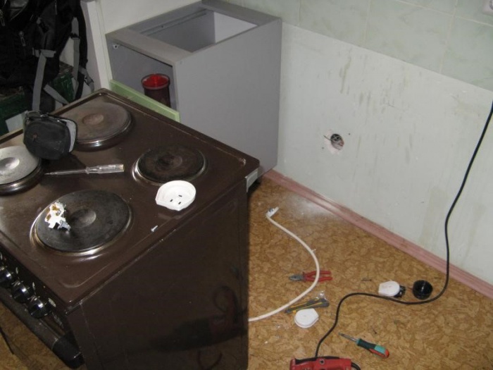
- The electric stove must be removed from the packaging and visually inspected for damage and contents.
- Next, disable old tiles and remove it.
- After studying the instructions and following its recommendations, determine the optimal location for your new household appliances.
Typically in slabs modern production The connecting cord is not included in the sale. This is due to the fact that it is preferable to connect devices using terminal blocks. Using such a connection, you can replace the machine with fuse links and connect the stove to a source of electricity using longer wires. The outlet is acceptable only if it can withstand a current of more than 32 amperes. Under no circumstances should you connect the electric stove to regular socket because she consumes a large number of current that a standard electrical network cannot withstand. To do this, you need to install a special cable and install a separate machine. It is prohibited to connect the device via a bug.
Instructions for connecting to a single-phase line

For correct execution connection procedure should be as follows:
- Turn off the circuit breaker responsible for powering the single-phase line;
- The power cable should not be more than 2 meters - this will allow you to move the stove if necessary;
- Then make sure that the cable is selected correctly and has required section and fuse, and then open the plug of the power supply unit of the electrical appliance;
- The stoves can be connected to three or single-phase power (in apartments the second option);
- In the space between the terminals, copper jumpers with a cross-section of 6 square meters are installed. mm, which are included with the stove;
- Next, you need to connect the phase, grounding and neutral conductors to the terminals. Make sure the bolted connection of the terminals is secure, otherwise it may cause a fire;
- The phase is determined by the indicator, zero - by the probe;
- A plug is fixed on the wire of the stove, under which a three-pin power socket is mounted;
- After inserting the plug into the socket, you need to make sure that there is no grounding using a tester;
- Then check availability short circuits between zero and phase in all operating modes of the device, with sufficient tester performance, you can start the machine;
- With a non-socket connection, the connection of the cores is made in a terminal box fixed to the wall surface with screws at a distance of 60 cm from the floor;
- Check the device for functionality: check each burner individually, as well as the ignition oven;
- When fully operational, you can begin operation.
Connection to a three-phase line

When connecting an electric stove in a rural private house, a three-phase connection can be used, the procedure will be slightly different:

In order to household device worked properly, it must be equipped with protective grounding. To do this, make sure that the housing electrical protection housing is also grounded. If grounding is completed, you can connect the grounding conductor to the housing. Never use a connection to service pipes as a ground connection.
The slab should be installed so that there is no possibility of contact between the body and elements that are not under tension.
This practically ends the process of installing an electric stove. If you are not confident in your abilities, you should seek help from specialists rather than risk your safety and the safety of your loved ones.
Video
The following video will tell you how to properly install and connect an electric stove:
This article will discuss connection diagrams for electric stoves, as well as practical guide How to install such a stove yourself. In addition, you can use help and order this service inexpensively. But if you are used to doing everything yourself, this article is for you. After reading the article in detail to the end, you will cope with this task without any problems.
All household appliances consume electricity, and naturally, when it comes to an electric stove, it is clear that connecting such devices requires mandatory grounding. Currently, sockets and plugs of the RSh-VSh standard are used on the market. These connectors have a ground contact. These sockets are available in both 220 V and 380 V. They were designed back in the days of the Soviet Union, and are still in use today, but time has made its own adjustments, modifying them for hidden wiring.
Brief content of the article.
Preparing to connect the electric stove.
Take your time, before you start connecting your electric stove, you need to read the instructions that came with it, namely, look at the power consumption and connection diagram options. And also make sure that all safety requirements and connection rules will be met. To do this you need:
Check the power cable. It must go directly from the electrical panel and have three wires for connecting to 220V or five wires for connecting to 380V. A grounding conductor must be present in any case.
Check the circuit breaker. For an electric stove, a separate 25-40A circuit breaker must be installed in the panel, depending on the number of phases in the cable that is connected to the stove. If it's 220V, it's usually 32A. If at 380V it is usually a 25A automatic machine.
Check cable cross-section. This item is required for those who have an old house with the old one aluminum wiring respectively. The fact is that in some old houses the electrical wiring is not designed for the power of modern stoves.
Table 1. To check the cross-section of the power cable for the power consumption of the electric stove.
|
Cable cross-section |
Copper conductors |
Aluminum conductors |
||||
|
Current, A |
Electric stove power, kW. |
Current, A |
Electric stove power, kW |
|||
|
220V |
380V |
220V |
380V |
|||
|
12,0 |
||||||
Check and label the wires. Modern wiring makes this task very easy, because the wires of the new type differ in color, most often the ground wire is insulated in green or yellow-green colors, zero of blue color, phase of white, red, brown. The old-style wiring presents not an easy task, because all the wires in it are the same color, which means that in order to determine which wire is grounding, you will need to turn off the power supply in the apartment.
Next, use an ohmmeter to check the wires; to do this, one probe must be secured so that it touches the battery and water pipe, the second one checks the wires. The ground resistance will be only a couple of tens of ohms, while the other wires will show much higher resistance. In order to somehow distinguish the wires, you should mark them with multi-colored markers or simple electrical tape, if you have it on hand. If you already had an electric stove or a socket for it, checking is not required, since everything is already connected to you, to its terminals. Without checking the wires and 100% identification of zero, ground and phase, connection is prohibited.
Sockets and cable for connecting an electric stove.
Depending on the chosen connection scheme, we may need 220V or 380V, following materials. Directly the socket itself, and a piece of cable. The tools include a set of screwdrivers, a knife, a multimeter and an indicator screwdriver.
Selecting an outlet for connecting an electric stove. The design of the finished pair completely eliminates the possibility of errors in connecting the electric stove. At the moment, RSh-VSh sockets are manufactured in Ukraine, and this has a bad effect on their quality. After all, they are designed to operate with a power of 7 kW, while most electric stoves produced these days are designed to operate with a power of 8-10 kW. Here, replacing the plug-socket pair will help us out, especially since nowadays there are wonderful sets of Belarusian production on the market. They are made in modern design and are suitable for both domestic stoves and European ones, which most often do not have cords and plugs in the connection kit.
Figure 1. Sockets for connecting an electric stove.
Belarusian connectors. The main advantage of Belarusian connectors is the combination of their price and quality. Undoubtedly, they are more expensive than Ukrainian ones, but much cheaper than their European counterparts. In their operation, they can withstand high powers and are designed to operate more than 32A; in addition, they are available on the market in versions for both open and closed wiring.
Connection via box, without socket.

Figure 2. Terminal box for connecting an electric stove.
IN modern houses, in new buildings, special terminal boxes are increasingly used to connect electric stoves. This connection option is universal and, unlike sockets, is suitable for connecting to both 220V and 380V.
In photo No. 2, a three-wire cable comes out of the wall and is connected to the corresponding contacts of the box (the contacts on the box are labeled). From the box, a flexible (black) cable goes to the electric stove.
Selecting the brand and cable cross-section.

Figure 3. Cable for connecting an electric stove.
Cable selection. To connect an electric stove, we also need a three-core or five-core copper flexible wire 1.5-2 meters long. I always take a cable of the PVS-3x4 or PVS-5x4 brand. The first number indicates the number of wires, the second number is the wire cross-section.
Electric stove connection diagrams.
Typically, when you remove the terminal cover from the back panel, you will find not only a row of copper jumpers, but also a circuit located next to it three options connections. They are designed for three-phase, two-phase and single-phase connection to the power supply. Next, we will consider in detail all existing connection schemes.

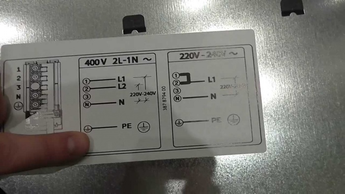
Figure 4. Sticker with options for electric stove connection diagrams. It is usually located on the back cover.
Connection diagram for a 220 V electric stove.
The most common option is to connect to single-phase network. To do this, you will need to install all jumpers in accordance with the figure. Namely, we place the two jumpers included in the kit between terminals 1,2,3 and connect the phase wire L1 to them. Next, we place a jumper between terminals 4.5 and connect the neutral wire N to them. There remains one terminal with a grounding symbol, and connect the PE grounding wire to it. It is advisable to comply color coding, that is, connect a blue wire to zero, yellow, green or yellow-green to ground, the remaining colors to the phase contact.

Figure 5.
Please note that on different models plates, the location of the grounding contact can be on either the right or left side. Therefore, when connecting a ground wire, be sure to check for the presence of a ground symbol next to the terminal.

Figure 6.
Connection diagram for a 380V electric stove.
There are two connection options: three-phase and two-phase. It is preferable to choose a three-phase option to evenly distribute the load. For a three-phase connection you will need a 5-pin socket, and for a two-phase connection you can purchase a 4-pin socket.
Three-phase connection.

Figure 7. Connection diagram for a 380 V electric stove to a three-phase network.
Let's first consider the three-phase connection option. We look at the diagram again and, in accordance with it, install only one jumper between terminals 4.5 and connect the neutral wire N to them. Next, we connect phase wires L1, L2, L3 to terminal 1,2,3. We connect the PE wire to the terminal with the grounding symbol.
Two-phase connection.

Figure 8. Connection diagram for a 380 V electric stove in two phases.
In accordance with the diagram, we connect phase wire L1 to terminal 1, install a jumper between terminals 2 and 3 and connect phase wire L2 to them. We install a jumper between terminals 4.5 and connect the neutral wire N to them. We connect the PE ground wire to the terminal with the ground symbol.
Attentive readers probably noticed in the picture that there is another option for connecting to three phases (on some models) without using a zero. This option was created for America; under no circumstances use it in Russia. The fact is that in this circuit the supply voltage should be 110V.

Figure 9. Three-phase connection diagram without using zero.
The final stage, verification.
Before plugging in the electric stove, you should turn on the machine and check that the connection to the outlet is correct. Using an indicator screwdriver, make sure that the phase wire is on the phase terminal. Check again that the wires on the plug are connected correctly. The resistance between the ground pin on the plug and the cooker body should be zero. Afterwards, you can connect the plug and slowly set all operating modes on the stove to make sure that the wiring can withstand the load. That is, the machine does not turn off and the cable does not heat up. So everything is great! You did it!
A kitchen stove, as practice shows, is largely a stationary device, and once you install it, you will not change its place every day or even once a week, and therefore there are schemes for connecting an electric stove directly, without a plug and socket. As a rule, in this case the electric stove is connected via junction box with carbolite or ceramic terminal block.
Video instructions for connecting an electric stove yourself.
Every year everything large quantity people decide to connect an electric stove. This is not surprising. Modern technologies, used in their creation, allow you to achieve considerable savings.
Let's imagine that you have already purchased an electric stove and you need to connect it. In this case, you must first carefully read the instructions. This is where the working connection diagram is indicated.
Attention ! Electric stoves consume a large amount of electrical energy compared to others household appliances, and this must be taken into account when connecting according to the diagram.
Connection algorithm
Before proceeding to directly connecting the electric stove according to the diagram, you need to familiarize yourself with a number of documents:
- PUE 7,
- PTEEP,
- technical certificate.
Only then will you be able to use these instructions correctly. Otherwise, you risk not only losing the warranty on the electric stove, but also putting yourself in danger.
Step 1. Select wires
The power wire according to the diagram must be independent. Simply put, it must be fed directly into the distribution panel. Otherwise, the wiring may simply burn out, thus causing a fire.
If you do not have a dedicated line in your home, then you can use the following types of wires:
- VVG-ng,
- SHVVP.
In turn, in order to connect the electric stove from the outlet according to the diagram, you need to use a PVA type cable. If you can't find it, then KG will do. By the way, the latter has much greater resistance to fractures. During operation, it can bend many times. There will be no harm from this.
When you select the cable cross-section for connecting an electric stove, you need to take into account three main parameters:
- number of phases,
- mains voltage,
- power consumption.
Just look at the table below and select the cable suitable for connecting the electric stove according to the diagram. In this case, it is better to provide a small power reserve, since fluctuations in the network are a common occurrence.

Also, when connecting an electric stove using a do-it-yourself circuit, you need to know about some nuances. Firstly, all operations must be carried out regardless of circuit breaker. Secondly, the current supply rating must be one unit higher than the device consumption.
You can find the technical characteristics of the electric stove in the relevant documentation, which should come with the device in the delivery kit. Also, all parameters are indicated on the case.
Attention ! The circuit breaker must belong to group C.
When connecting an electric stove according to the diagram, you must take care of the presence of an RCD. It will protect you and your family from electric shock during operation of the device.
The RCD must be installed near the circuit breaker. Connecting a residual current device is possible only after installing a circuit breaker. Special attention pay attention to screw terminals. They must be securely fixed.
Step 2. Making a socket
Ideally, you should already have an outlet in your kitchen through which you can connect the electric stove according to the diagram. But unfortunately, the connectors required power Not all apartments are equipped, so sometimes you have to take care of this yourself.
Attention ! You need an outlet that can provide power to electrical equipment with a power of over 3 kW.
In most cases, a single-phase socket is installed in the kitchen. It is more than enough to connect the electric stove via standard scheme. At the same time, the minimum rated current must be at least 32 A. Ideally you need 40.
The socket that you will use to connect the electric stove according to the diagram must be made with quality materials. Electrical contact must also be ensured.
It is very important that the number of cores is the same as the number of wires. Under no circumstances should wires be connected together to allow connection to a single terminal. This may lead to a fire hazard.
When connecting, you may only use copper wire. In this case, the cross-section of the wire must correspond to the table values. The outlet itself must be installed on a flat surface. However, there should be no highly flammable materials nearby.
Advice ! When installed on brick wall It is advisable to use a gasket to prevent the base of the socket from cracking.
You cannot install a socket for connecting an electric stove according to the diagram near the washbasin. This does not comply with safety regulations. Splashes can get on the exposed cable and cause a short circuit.
Also, the socket should not be installed too close to iron pipes. The same applies to doors and window openings. From the right choice installation location depends safe operation device.
When you finish installing the socket for connecting the electric stove according to the diagram, check the insulation. The cables must not be damaged. Only then turn on the stove.
Attention ! Ideally, the colors of the wires in the plug should match the colors of the cables in the socket.
Pay special attention to the screw terminals, they must be secured properly. Moreover, when installing an outlet, to connect an electric stove, each multi-core cable must be additionally soldered. Soldering must be done where they are attached to the contacts.
A multimeter will help you check how correctly you have connected the wires. Once the preliminary check is completed, the circuit breaker can be turned on.
Step 3. Connecting to the stove

To connect the electric stove to the power cable, you will, of course, need a circuit diagram. The exact connection drawing must be in the technical data sheet. Once you find it, you will need to find the small cover on the back panel and unscrew it. Underneath you will find the wire terminals.
Now you can secure the wires to connect the electric stove according to the diagram. But before that, you need to secure all the cables. Otherwise, with a careless movement you will simply tear them out.
Attention ! There are special clamps for fastening on the body of the electric stove.
The connection of wires depends on the number of phases. For pairing you need to use copper jumpers. They usually come with the terminal block. Make connections according to the diagram you have. After this, tighten the screws.
Usually in the documentation or on the cover itself there is a diagram with which you can connect the stove. Wherein The colors of the connected cables should ideally match each other.
First of all, you need to connect the ground. Usually this wire has light green color(a mixture of yellow and green). After this you can connect the neutral. The blue cable is connected third. Only after this can you move on to the phase wires. The sequence is as follows:
- brown,
- black,
- black.
Extreme caution must be maintained during the connection process, as incorrect contact can lead to failure of the plate or wiring. At the end of the work the lid is closed.
General network connection diagrams

Perhaps this is the most simple circuit connection to a single-phase network, in order to connect the power you will need:
- Install jumpers on terminals L1 and L2, L2 and L3.
- Connect to L2 brown wire under phase.
- Install a jumper on N1 and N2.
- Connect neutral to N2.
- The grounding wire is connected to the grounding contact.
However, you must remember that this general scheme. Many diagrams that come with the documentation may have different terminal names.. Moreover, even their number may be different.
If you need to connect the stove to three-phase network, then the scheme will be slightly different. You will have three phases that you simply need to connect to the three terminals L1-L3. In this case, no jumpers are needed during the installation process. N1 and N2 together with PE are connected to the advisory contacts.
With a two-phase network, you will need to install a jumper on L1 and L2. After this, you can connect phase A to them. Accordingly, L3 will output to C. All other wires can be connected in the same way as previous networks.
Results
Connecting an electric stove to the network is not so difficult. Moreover, this is possible in apartments and houses where the design did not provide sockets of this type. But to make this possible, it is necessary to use high-quality components and take into account important nuances like the number of phases in the network.
The other day, I had to deal with the repair of the Dream electric stove, or more precisely, with the repair of the oven of this product.
According to the stories of the owners of this miracle, the stove periodically lives its own life, then one burner does not work, after a while it starts working, but the other does not respond. The oven laboriously fed its household for new year holidays, and for Christmas she flatly refused to bake a goose. I found her in this state. When the oven was turned on, the stove only responded by lighting the oven; it categorically refused to provide heat, much less bake pies.
Having arrived at the call, I was not particularly prepared for the global repair of the Mechta 12-03 electric stove (by the way, the disconnection principle is similar to other models). I took with me a traveling box with necessary tools and went to apply.
A quick inspection of the main electrical connections of the stove yielded no results. Everything was in place and in very satisfactory condition. OK. Absence quick results- also a result. Next I followed the standard chain from the power incoming distribution terminals. Along the chain, I checked the thermostat of the Mechta electric stove - no complaints, and slowly but surely following the visual diagram, got close to the power switch PM-16-5-01.
I immediately realized that zero did not pass through it, but I did not remove the switch or solve the puzzles of the zigzags of the five-speed switch, having decided to prepare myself and approach the process creatively.
Just as I quickly discovered a malfunction of the Mechta electric stove oven, I was unable to find a wiring diagram for this miracle of technology. But I found more important, the operating modes of the five-pin power switch. As for the Dream electric stove circuit, the issue was resolved as follows. Although I had a visual, and most importantly not broken by anyone before me, diagram, having made a request to the manufacturer, to my surprise, I received an answer quite quickly, and then wiring diagram electric stove Dream 12-03, for which special thanks to the manager Natalya from this production.
Armed with the diagrams, I made a repeated attack on the repairs electric oven miracle slab Dream.
My initial assumptions were confirmed, the fault was hidden in the oven mode switch, and more specifically, two contacts “floated” to the side due to heating, and the contact plates had a reddened appearance from overheating. Verdict - the power switch for the Dream oven modes needs to be replaced.
But, since in our city there were no such switches in stock, only on order, at the request of the owners of the stove “to do at least something,” the outgoing contacts were restored to their place by heating, and the contact surfaces themselves were cleaned of charring with alcohol, (fortunately, their surface was not damaged when burned).
As an option, for the temporary operability of the power switch PM-16-5-01 and others from the same series, if the “burnt” contact has become deformed due to temperature and does not close the contact plate, it can be bent. This cannot be done locally, but by removing the contact group from the body, having first pulled out the contact jumper holding it (indicated by the arrow in the photo), it is possible to bend it.
At the same time, taking into account temperature deformation and weakening of the metal, take the bending angle 20 degrees greater than the adjacent working contacts. Before installing the switch on electric stove Dream, make sure that according to the operating modes, the “treated” contact closes the group, and in other modes there is a visible gap.
It is difficult to give a guarantee for such repairs of the Dream electric stove, but until the arrival of a new power switch, it will definitely last.
At the end of my description of how to repair an electric stove, I will post all the diagrams that I was able to find on the Internet and those sent by the manufacturer (by the way, in my case, the actual installation differed from the factory diagram).
Diagram of contact groups of power switch PM-16-5-01

This is what the oven switch itself (and the burners) of the Dream electric stove looks like:

Electrical diagram of an electric stove with a Dream oven (although it has two burners, the wiring of the oven switch is the same.

Wiring diagram for electrical connections of the Dream 8 electric stove

Electrical connection diagram for electric stove Dream 12-03

Electrical diagram of a two-burner stove with oven model “Dream 221CH”

Electrical diagram of the stove model “Dream 29”

Click Class
Tell VK
Dear visitors!!!
Analyzing your questions, which mostly affect the repair and connection of electric stoves, it became necessary to publish an additional topic on this topic. Having understood all of the above, in general, as regards this blog, you will receive necessary knowledge and, accordingly, then you will make your own decisions in eliminating breakdowns both on electric stoves and other household appliances.
I consider my goal to be to convey my knowledge and experience in solving one or another task assigned to you - to eliminate any malfunction. This topic will be like a reference for you to resolve any issue that may arise regarding the repair of electric stoves.
Electric stove Electra 1006
So, you have purchased a household stationary electric stove designed for cooking:
- stewing vegetable, fish and meat dishes;
- frying;
- cooking;
- drying fruits, mushrooms and vegetables.
Convenience is created by the fact that, for example, using a high-temperature heater \grill\ and a gearmotor with a spit, you can prepare:
- chicken on a spit,
- kebabs
etc.
Of course, before you start using this or that electric stove, you should carefully read the technical data sheet “Operation Manual” and, accordingly, follow the specified recommendations.
It should be remembered that connecting an electric stove to an external alternating voltage source \outlet\ without grounding is not allowed.
Repairs or diagnostics of the electric stove should be carried out in compliance with safety precautions, that is, by first disconnecting the plug from the outlet. As a basis for this training topic, we will consider the electrical circuit of the Electra 1001m power supply.
That is, we need to understand the essence of all electrical connections. The topic, I would say, is very significant for us. For example, in the event of any malfunction, it is necessary to change the same burner. What needs to be taken into account? Does the installed burner correspond to the power specified in the instruction manual?
Next, you need to replace the burner power switch. Which terminals \contacts\ of the power switch should the wires be connected to? How to properly connect the burner to the wires? How to properly connect two heating elements \upper and lower heating elements\ of the oven? How to correctly connect two oven heating elements in an electrical circuit?
How to replace:
- electric burner warning light;
- oven warning light;
- oven lighting lamp.
Or let’s say, how to replace a key switch for an electric stove? Here, as it were, the topic is quite difficult - both in carrying out repairs and in correct connection.
Changed for example network cable with a plug, - do the contact connections correspond to the power plug with contacts power socket? I may be missing something on this topic too. I believe that in our lives we should be inquisitive, interested in one or another source of information that has not a negative, but a positive side in its content.
And we need to convince ourselves that:
- you will succeed;
- You will be able to make your decision;
- You will find the necessary source of information;
- You will become experts in this area.
In fact, to understand, we are already them as such - if we are interested in issues related to electrical engineering. If we... are currently interested in:
- technical sites;
- technical literature.
And so, to the point. I will try to present everything separately, for each electrical connection, for each individual section of the electrical circuit.
Electrical diagram of an electric stove - “Electra 101m”

What exactly is this electrical diagram of the Electra 1001 m electric stove? There is nothing supernova or incomprehensible here, it is necessary:
- learn; learn
- remember all electrical connections;
- understand the essence of these connections,
- included in the electrical circuit of the electric stove. Having understood, for example, this electrical circuit, you can repair absolutely any electric stove.
In front of us in the photograph is an image of two heating elements of the oven, the so-called heating elements.

Double top heating element for oven, power - 0.8 kW

Lower heating element of the oven, power - 1 kW
If it is necessary to replace heating elements in the oven, their power is taken into account first of all. Let’s say that these two heating elements from other modifications of ovens may well fit the Electra 1001m electric stove; in terms of their power, they are quite suitable. In my practice, I had to change the plate heating element from the oven to a tubular heating element. Of course, for this we had to adapt and secure the heating element.
Replacing the heating element of an electric stove
When replacing a heating element with the appropriate power for an electric stove, you need to take into account that the contact connections of the two wires with the heating element do not touch the body of the electric stove, that is, the contacts must be insulated either with cambric or electrical tape.
How to check the heating element or how to test the heating element?
To do this, take an “Ohmmeter” or “Multimeter” device \having previously set the device to measure resistance\, connect two wires with connectors to the corresponding sockets of the device, turn on the device and touch the contacts of the heating element with two probes. For example, the display of a digital multimeter will indicate either a break \unsuitability of the heating element\, or the presence of resistance of the heating element.
You have replaced the heating element of the oven. How to check whether the wire connections are made correctly when replacing the heating element? This is the “heart,” so to speak, when diagnosing. We carry out diagnostics passively - without connecting to an external source. Yet again:
- take the device;
- turn off the entire load of the electric stove;
- turn on only the oven power switch;
- We connect two probes of the device to the contacts of the plug.
The display of the device will indicate the presence of exactly the resistance to which the oven power switch was set.
We seem to have already figured out the heating elements of the oven. Let's go further, the next heating element of the electric stove is the electric burner.

Cast iron electric burner, with pressed rim
Electric burner diagram

Electric burner diagram
According to the electrical diagram of a cast-iron burner, we clearly have the opportunity to trace the connection diagram of the three filament spirals - the heating element.
As you noticed, in addition to the three filament coils, the circuit includes an open contact that regulates the heating temperature of the burner and prevents the burner from overheating. What is this element that prevents the burner from overheating?
The operating principle of this element is based on the operating principle of a thermal relay, that is, closing and opening in the electrical circuit occurs due to the effect of temperature on a bimetallic plate with contacts.
Reading the electric stove diagram:
The wiring diagram of the electric stove is made in a single-phase design with the three left \1, 2, 3\ and the next two \4, 5\ terminals short-circuited at the input.
There is also a separate terminal - a grounding terminal.
Let's trace individual areas electrical connection grounding wires for electric stove Electra 1001m. Are the wires that are needed for grounding metal parts Are the housings also an electrical connection? - You ask.
- Yes, because given protective grounding creates a decrease in current in the human body when touching an electric stove that is energized due to a violation of the insulation of one of the wires.
So, from the electric stove panel \where the network cable is connected to the electric stove\ two grounding wires come off. One wire from the ground terminal has a series connection:
- with gear motor housing;
- with the body of the first electric burner \as indicated in the diagram\;
- with the housing of the third electric burner;
- with the housing of the fourth electric burner;
- with the housing of the second electric burner
The other wire from the ground terminal is also connected in series with heating elements Heating elements of the oven:
- H7 and H6,
The body of the electric stove is metal, so not only the control panel and other parts are grounded, but also the entire metal body of the electric stove itself.
Explanation of the electrical diagram - electric stoves
We have figured out the grounding of the electric stove, read the diagram further:
For the convenience of presenting thoughts, let’s assume that three short-circuited inputs \the first, second and third terminals\ on the electric stove panel are connected to the phase.
Two shorted inputs \the fifth and fourth terminals\ are connected to the neutral.
Let's look at the diagram:
Terminal 5 of the electric stove panel has a branch of two wires. One wire from terminal 5 (neutral) is connected to PS contact A three-stage oven switch.
The other wire from terminal 5 is connected to P2 contact A seven-position power switch for the second electric burner H2.
There are two wires connected to terminal 4 (neutral). One wire in serial connection through a gearmotor it is connected to the first contact of the electric stove key switch.
The other wire from terminal 4 is connected to the light bulb socket contact L7. From this light bulb contact L7 branch - the wire is connected to P3 contact A power switch for the third burner.
From the second contact of the electric light bulb socket, the wire is connected to the second contact of the electric stove key switch.
The electric stove key switch for this circuit switches from a neutral central position - with the closing and opening of sections of the electrical circuit into two wires, two wires of which are connected to the \4\ terminal of the panel.
A phase is connected to the three shorted inputs (3, 2, 1) of the panel, as we have already agreed. From terminal 3 of the shield, the phase wire is connected to P1 contact IN seven-position electric burner power switch H1.
From terminal 2 of the shield, the phase wire is connected to PS contact IN oven power switch.
From terminal 1 phase wire is connected to P3 contact IN power switch for the third electric burner.
We looked at how it works Electric Energy on the power switch ПШ - a three-stage switch of the frying electric cabinet, as well as on seven-position power switches:
- P1 - for the first electric burner \H1\;
- P2 - for the second electric burner \H2\;
- P3 - for the third electric burner \H3\;
- P4 - for the fourth electric burner \H4\.

seven-position power switch for electric burner PM - 7
It is necessary to understand the nature of such electrical connections, namely, as you have already drawn your attention to, for all power switches the phase wires are connected to the contacts IN(look at the diagram).
Neutral wires are connected to contacts A(power switches).
We turn our attention to the seven-position power switches for the electric burners (see the diagram):
For all four seven-position burner power switches, an ordered value is established for the contact connections of the power switches with the contact connections of the electric burners.
That is, the wire from contact 1 of the burner power switch is connected to the upper first contact of the electric burner.
The wire from contact 2 of the burner power switch is connected to the second contact of the electric burner and further.
The oven thermostat in the electrical circuit is connected in series, from pin 1 PSh, that is, the thermostat performs the function of the same thermal relay. The signal light L6 of the thermostat is connected in an electrical circuit - in parallel to the contacts of the power switch of the PSh oven:
- number 3;
- number 4 (through oven heating elements).

oven thermostat

three position oven switch
Bulbs:
- connected in parallel to contacts:
- letter B (phase);
- number 5 (neutral),
— burner power switches.
Consequently, burnt-out power switch bulbs for electric burners do not in any way affect the operation of the burners.
It is precisely all of this that has been stated that you need to understand, understand... and then repairing any electric stove will be just fun for you. That is, you need to carefully trace all the connections in the electrical circuit.
The same operating principle applies to the three-stage power switch of the electric fryer. Let's look at the diagram:
The wire from contact 3 PS is connected to the first contact of heating elements H6 and H5. Contact 2 of the oven power switch is connected by wire to the first contact of heating element H7.
The wire from contact 4 PS is connected to the second contacts of the heating elements:
Next time we will deal with other electrical circuits of electric stoves.
That's all for now. Follow the section.
Tweet
Tell VK
Click Class
-
Hello Oleg. I don’t even know what kind of electric burners we’re talking about? There are different types of burners:
cast iron electric burner;
electric burner for glass-ceramic surface,
burner with halogen lamps
and further. I also do not know the name of the electric stove and its model. Therefore, it is difficult for me to navigate your question.
Victor.-
Hello, Victor.
Email stove De Luxe 5004.04e. Yesterday I changed 145.1 kW and 180.1.5 kW. Cast iron. Marking of original pins 1-2-4-3. Acquired, 1243 and 1234. Commuted by numbers. There is another cast iron pancake. 1 kW, 145, manufactured in 1985. Three-pin. I would like recommendations for installation in the above stove.
Oleg.
-
-
Hello. It is advisable to install and connect electrical outlet, which would fit a three-prong plug, is the best and simplest option. When connecting a socket, it is necessary that there is correspondence between the contacts of the socket and the plug (phase-phase, neutral-neutral, ground-ground). If you don't replace the four-prong outlet, you will have to replace the plug. In this example, you will need to ring the wires - for them correct connection to the contact bars of the electric stove. In both examples given, you must not confuse zero with ground.
Hello! I have gas stove with electric oven. In winter, mice made a home for themselves in the insulation of my oven)). We took it apart and cleaned everything. What will replace this insulation now? Help me please.
Dear Victor, hello! I am making a homemade electric stove for 2000 watts. Switch from the old “Lysva” with 7 positions. If I understand correctly, the power switching stages should look like this: 2000,1600,1200,800,400,200. But if you connect the burner according to the pin numbering, you get this layout: 2000,1200,1200,800,800,200. Please tell me why this is the situation? The electrical circuit is taken for Lysva. When you try to swap the 3rd and 4th burner pins, it turns out like this: 2000,1200,800,400,200, and the last position is unexpectedly 800! Help me figure it out, I’ve broken my head (my own), but nothing works. Thanks in advance! Sincerely, Alexander.
Excellently told, everything is simple, without unnecessary incomprehensible words - thank you, it was very helpful, I just old stove I'm restoring. there's just a bunch of wires and that's it, I think I'll finish this information tomorrow)))
You probably can’t tell me how to connect a 3-pin burner instead of a 4-pin burner. because this is a violation of the scheme.
Hello. Can you tell me what type of signal lamps are in this stove? One of my lights is not on, I started to find out the reasons and, when I wanted to measure the resistance of the remaining workers (after unscrewing it), the multimeter showed a break (it set the measurement limit to megaohms). Naturally, a burnt-out one doesn’t “ring” either.
That's it, the issue is resolved) Neon lamp IN-21. When moving and twisting and unscrewing, apparently the non-contact disappeared and the lamp lit up
I have an Electra1006 electric stove. Everything works except the oven and the large burner. What should I do? Thank you.
Instead of the Electra-1102 stove (4-pin plug, as well as a socket), I bought an Evi-417 (3-pin plug). The whole house is equipped with electric stoves (without gas). What is the best and easiest way to connect Evi-417?
Hello, please tell me why the oven signal light is on when the oven switch is off. Electra 1001m stove, when you turn on the oven, the signal light goes out and the switch on light comes on like a burner. I changed the phase with the zero in the plug; the signal light does not light up at all, either when the switch is on or off. Wiring single-phase 220 V.
Thank you for the advice on connecting Evi-417 in Zelenograd! Everyone is alive, everyone is happy!
Keywords that were missing:
1) marking of contacts INSIDE the plug
2) the plug says 380V - ignore it, connected as 220V
3) wires P and N can be swapped (read on your website)
4) the main thing is not to confuse the Earth with the Neutral (for a former metrologist this is intuitively clear)
electrical burner diagram, between contacts 1 and 4 there is a disconnect contact, very interesting, is this contact mounted inside the burner or somewhere else, based on the diagram of the burner itself, or I didn’t understand something, if it’s built in, then dismantling is possible or not , and one more question - how can you check these four outputs, ring them by unplugging the incoming wires?
thank you very much for helping me figure it out
Hello!
Please tell me how you can transfer the current collector plug (4 contacts) from Electra-1001m to Electra-1002 (3 contacts). 4-pin socket in the wall.
Sincerely!


