Electrical wiring for an electric stove has certain features. After all, this is often the most powerful consumer electrical energy in the apartment. In this regard, the risks associated with wrong choice sections or poor quality installation, increase sharply. Therefore, in order to avoid sad consequences, we advise you to familiarize yourself with the basic rules for installing wiring for an electric stove.
First of all, you should dwell on the rules for connecting and installing the wiring of an electric stove. After all, the requirements for its cross-section directly depend on this factor.
Electric stove connection diagram
Let's start with possible options for connecting an electric stove to electrical network. There are two possible options - connecting to single-phase network and to three-phase network.

So:
- Connection to three-phase five wired network has a lot of advantages. Firstly, this is faster heating of the electric stove, secondly, there is less load on the wire, and thirdly, there is an almost completely absent voltage drop even when the electric furnace is operating at full load.
- The main disadvantage of such a connection is the price, which is much higher for connecting a three-phase network. In addition, we can note a certain complexity in arranging such a connection, as well as the requirements for the person operating such a network. Often these problems become insurmountable.
- In this regard, a single-phase connection of an electric stove is much more often used. Which, in addition to accessibility, is inferior in all respects to a three-phase network. Single-phase connection is made with three wires.
Pay attention! In some cases, a two-phase connection to an electric stove is possible. In terms of its parameters, it practically does not differ from three-phase and has the same advantages and disadvantages. A two-phase connection is made with four wires.
- As for the connection diagram, it is identical for networks with any number of phases. From the input machine, the electric oven is connected through a separate group machine. In some cases, as additional protection it is equipped RCD automatically. But its presence is not necessary.
- Usually the instructions provide for the presence of an outlet. This also applies to networks of any voltage. But recently it is increasingly being abandoned as an unreliable contact connection. In principle, this is not prohibited by the rules.
- If you decide to abandon the socket, then it is better to abandon other contact connections such as terminal blocks, and make the connection with a solid cable from the group circuit breaker to the electric stove.
Requirements for the connection diagram of an electric furnace
Now let's talk about the connection requirements electric oven. In principle, they are quite logical and do not require special measures.

- Let's start with the introductory machine. According to clause 9.6 of VSN 59 - 88, the introductory machine for an apartment or house with an electric stove must be designed for rated current at 40A. But this only applies to a single-phase network. In the case of a three-phase (two-phase) connection, the rated current of the input circuit breaker is determined by the technical conditions.
- Further, according to clause 7.2 of VSN 59 - 88, a separate group must be organized to power the electric stove. This group must be powered in accordance with clause 9.6 of VSN 59 - 88 from a group circuit breaker with a rated current of 25A. This again only applies to single-phase connections.
- Electrical wiring for an electric stove must comply with PUE standards and in brick, concrete and reinforced concrete rooms must be carried out in a hidden way. Open way It is advisable to lay wiring to an electric furnace only in rooms made of flammable materials.
- The socket for an electric stove in accordance with clause 12.27 of VSN 59 - 88 must be designed for a rated current of 25A. Moreover, it must have a grounding contact, as demonstrated in the video.
People who have electric stoves that have served for decades are often interested in connection diagrams for the burners. This is not surprising, because over time these elements fail, and the only way to fix everything is to install new burners.
In theory, at ideal conditions In operation, burners can last almost forever, but, of course, this does not happen. The fact is that we often forget to turn them off, which causes the heating elements to heat up to unimaginable temperatures. In some cases, you can even see cracks on the surface of burnt-out burners. But this only applies to older models; this does not happen with new ones.
When a stove burner burns out, the owner has to think about connecting a new element. It goes without saying that you can’t do without a diagram. Of course, it should be in the technical data sheet of the product. But we must admit that after 20 years, documents are lost or become unreadable.
Attention ! Ideally, you should connect the new burner to the electric stove exactly according to the diagram indicated in the technical data sheet.
Connection diagrams for popular stoves
Dream 8

This is one of the best selling slabs of the past. It’s not surprising that you can see it in many people’s kitchens. It consists of the following key nodes:
- Heating element E1+ E2,
- Heating element E3-E5,
- S1-S4,
- indicators.
Heating elements E1-2 are located in burners 1 and 2, respectively. This can be easily seen in the diagram in technical documentation slabs TEN E3-E5 is an oven. S1-S4 are a switching unit with which you can control the electric stove.
The indicators available in the electric stove, according to the diagram, are of two types HL1 and HL. They are responsible for the operation of heating elements. Also available HL3. But this is just illumination of the oven, so that you can always see the condition of the dish.
Attention ! Most designs use a T-300 thermal relay. Moreover, the power of each heating element is 1 kW.
Switch S1 is responsible for adjusting the degree of heating. It has four positions with which you can provide different intensity of fire. In the first position, P1-2 and P2-3 are closed.
When this happens, heating element E3 is activated. In this case, the current will travel the following route:
- it all starts with contact XP,
- then comes relay F,
- P1-2,
- E4-5 + E3,
- P2-3.
The first destination is the plug pin. This heating element has serial connection to the fourth heating element and to the fifth. Moreover, it is connected in parallel to the second and third. You can easily verify all this for yourself by looking at the diagram below.
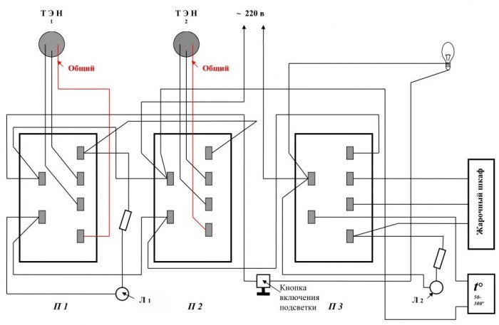
When switching to position number two occurs, P1-1 and P2-3 are activated. Naturally, the circuit through which the current passes changes. It all starts with the plug contact located at the bottom, which is labeled as XP. Then the following intermediate points follow:
- P1-1,
- P2-3.
It all ends with the XP plug on top. When this circuit is activated, exclusively heating element E3 is started. An increase in power can be achieved by reducing resistance. The main advantage of this scheme for connecting an electric stove burner is that it is possible with a constant network voltage, which is 220 V.
For S1 there is position number 3. In this case, P1-1 and P2-2 are closed. Because of this, the E4+5 heating elements are connected. If we talk about S4, then this switch is responsible for the operation of the lamp. On standard scheme operation of electric stove burners, it is designated HL3.
Electra 1002

The second, most frequently used electric stove in homes and apartments is Electra 1002. Therefore, knowing about its burner connection diagram is simply necessary. Fortunately, it is not particularly difficult and even a beginner can figure it out.
So, the electric stove has four burners; naturally, each of them has its own connection diagram. The first two heating elements are indexed H1 and H2. Their main difference is their tubular structure.
The third burner in the electric stove connection diagram has the index H3. It is made of cast iron and is quite large - 200 mm. H4 is also made from cast iron. Its size is 145 mm.
Regulators P1 and P2 are responsible for adjusting the temperature. They do not have power levels as such. But this drawback is more than compensated for by the seven-speed switches P3 and P4. In turn, the PSh is responsible for the oven and has 3 positions.
Switch P5 is responsible for blocking. The signal lamps for the burners in the electric stove circuit are L1-4. The fifth L allows you to illuminate the oven. Also available L6. It turns on when the appropriate temperature is reached in the cabinet.
For heating oven elements H5-6 correspond respectively. Seven is a grill. The thermostat is designated by the simple letter T. There is also a key switch - this is B. The seventh L illuminates the oven.
Attention ! The gearmotor is designated as capital letter M.
Schemes for other popular models

Of course, electric stoves Electra 1002 and Dream 8 were one of the most popular in their time. But now people prefer to buy products from completely different brands; among the most famous are Gorenje and Hansa. It is their stoves that most people install in their kitchens.
You can also remember the Lysva brand. Of course, few people now buy their stoves if they have the opportunity to purchase products from a more respectable brand, however, the company has a fairly large circle of consumers. In general, below you will find wiring diagrams for electric stove burners from the most popular brands.

With this diagram for connecting electric stove burners, you can easily do all the work yourself. But for their quality implementation it would not hurt to at least basic knowledge operation of electrical networks and electrical appliances.
The nuances of connecting the heating element and checking it

The heating element provides normal work electric stove burners. In fact, this is its main element, without which the normal functioning of the entire circuit is impossible. But for everything to go smoothly, it is necessary to take into account many nuances. Among the main ones:
- The contact connections should not touch the body of the electric stove, otherwise the connection may end disastrously.
- The contacts must be properly insulated. Cambric is best suited for this purpose. As a last resort, you can use regular electrical tape. But its reliability is much worse.
- It is very important to test the heating element of the electric stove burner so that the connection according to the diagram is successful.
To test the heating element of an electric stove burner you will need a special device. It's called an ohmmeter. A multimeter is also quite suitable for this purpose. These devices are designed to measure resistance in a circuit.
If you are using a multimeter, then first you need to set the appropriate measurement mode. Next, the two wires must be connected to the corresponding sockets.
After this, you need to turn on the device. Using two probes you can measure the resistance of heating elements. To do this, you need to use probes to connect the electric stove burner to the contacts of the heating element.
If your measuring device is a digital multimeter, then after connecting its probes to the contacts, the display will immediately show the result. Three positions are possible:
- gap,
- complete unsuitability
- resistance.
Of course, in order to connect the heating element of the burner to the electric stove according to the diagram, it is necessary for the multimeter to show the third position. Otherwise, nothing will work.
After connecting the heating element of an electric stove, each person has a question: will the burner work after this? Are all wires connected correctly? This is especially true when it comes to burners.
Attention ! Diagnostics of connecting all wires of the heating element to general scheme Electric stoves must be operated in a passive state.
For diagnostics you will need the same device. Before testing, the load of the electric stove is turned off, the power switch is turned on and the probes are connected to the plug. The display will show the corresponding result.
Results
It is not difficult to connect the burner and all its elements to the electric stove according to the diagram. It is enough to have an appropriate diagram and basic knowledge of the functioning of the electrical network and electric stove.
Thanks to such universal energy as electricity, the popularity of electric stoves is increasing. This site has an article on how to connect an electric stove, and this page describes common problems, methods for identifying and eliminating them.
In many cases, home handyman or an ordinary user can repair the electric stove himself without resorting to the expensive services of a specialist.
Cooking on an electric stove
Troubleshooting algorithm
Regardless of the model of the electric stove and the type of burners used, identifying the cause of the failure of the electric stove should be done using the following algorithm:

 Troubleshooting an electric stove
 The task of any repairman is localize the problem. Having gone through this algorithm step by step, you can repair the electric stove with your own hands, having in stock small set tools and having limited knowledge of electrical engineering.
Necessary conditions for self-repair
The most an important condition, on which depends not only successful renovation electric stoves, but also the safety of the master and others - this is knowledge of the basics of electrical engineering and electrical safety. Confidence in your abilities is also necessary - some measurements will have to be made with the voltage turned on.
To disassemble the body of the electric stove, you will need screwdrivers with suitable blades, possibly a set of keys, and pliers. To work inside the case, depending on the identified malfunction, you will need a soldering iron, wire cutters, insulating tape or.
 Set of repair tools
 Sometimes it is possible to identify a problem only by visual inspection (carbon deposits on the contacts, or a loose wire). But practice shows that in most cases it is impossible to repair an electric stove without measuring instruments.
 Inspect terminal connections
 The most acceptable would be to use a multifunctional measuring instrument, which should be in use by any master dealing with electrical engineering. In some cases, you can get by with a voltage probe and a homemade dialer using a light bulb and battery.
Superficial diagnostics of an electric stove
If the mains voltage is normal, but the stove suddenly stops working after switching on, then it is worth checking the socket itself - perhaps it does not correspond to the power, or the contacts are worn out and they spontaneously bend during the heating process.
There are cases that in electric stoves with mechanical regulators and burner power switches, the control light burned out long ago, and the stove itself stopped working properly much later. On at this stage, without starting to disassemble the case, you can identify a malfunction in the switches, including various burners and switching modes their work.
 Two electric stove burners are not working
 If it is discovered that some of the heaters are working, although not at full power, then a malfunction of the power cord can be ruled out, and you need to look for problems in the switches or in the burner spirals.
It is unlikely that all the burners will burn out at the same time (although this is possible if all the heaters were working during the power surge). Therefore, if there is no response to manipulation of the switches, voltage may not be supplied to the controls.
Disassembling the body of an electric stove
Since electric stoves and hobs there are the most different forms, dimensions and designs, there is no way to describe them all in one article, so the user must independently figure out how to disassemble the case. But what is common to all types of electric stoves is the presence of thermal insulation and it must be handled very carefully.
 Various designs electric stoves
 If the thermal insulation layer of the electric stove is significantly damaged, its energy efficiency will decrease, and the readings of the temperature sensors will also change, which will entail incorrect operation slabs in the future.
It must be remembered that working with glass wool thermal insulation should only be done with thick gloves, and asbestos dust from the thermal insulation gaskets of old electric stoves is harmful to health.
Checking the incoming voltage
Having disassembled the body of the electric stove, it is necessary to study internal structure equipment, determine the type of regulators, switches and heaters. It will be very useful to have it in stock slab diagram. But even without a diagram, if you know the basics of electrical engineering, you can understand the heater control system and identify the problem.
Attention, the following verification methods are contrary to the user instructions, which prohibit turning on the electric stove when the housing is disassembled, so you should be very careful!
If the electric stove does not work at all, you should check the presence of voltage at the input of the switches or the electronic control circuit. Imported electric stoves with an electronic control unit are vulnerable to power surges, and very often problems with them are not related to damage heating elements.
 Electronic control unit for electric stove
 If the power cord is OK and there is power, but the display does not light up, then the internal fuse of the electric stove control unit may have blown. But the indication of a working display does not always guarantee its functionality - there may be a breakdown in the power switching relays.
Most affordable way checking the control unit is to check the voltage supply to the terminals of the burner heaters. If the voltage is supplied, but the heating element does not heat up, then you need to disconnect the electric stove from the outlet, then disconnect the terminals from the heating elements, and ring them.
 Checking the voltage supply to the burner spiral terminals
 It will be safer if you first attach special crocodile clips to the terminals of the heating elements, put on the test leads, and then apply voltage. If only some of the burners are working, then it would be more advisable to first ring the heaters, and only then look for an open circuit in the power circuit. It must be remembered that heating elements can have several spirals - the way they are connected together regulates the heating power.
If a burnt-out filament coil or a breakdown in the housing is detected, the damaged heating element should be replace.
If the stove is old, then it is worth replacing the burnt-out heaters with more advanced and economical ones. New electric heaters for electric stoves have proven themselves to be the best.
If testing the spirals does not reveal any malfunctions in them, then the cause should be sought in the control unit. As already mentioned, heating elements can have several built-in spirals, which are switched using switches or electronic relays. In both cases, a large current flows through the contact groups, causing carbon deposits to form on them.
 Electric stove operating mode switch
 Operation of a heating element with multiple coils
Let's say the heating element of an electric stove has two spirals: C1 and C2. To switch them, a three-position switch with three contacts can be used: K1, K2, K3.
 Connection diagram for a heating element with two spirals
 When K3 is turned on, both spirals are connected in series and will operate at half their capacity. When K2 is turned on, coil C1 will heat at full strength. Maximum heating will be obtained by simultaneously closing K1 and K2 - the two spirals will be connected in parallel. All others possible options have no meaning and should be eliminated by the switch design itself.
To repair such a switch, you need to disassemble it and get to the contacts to clean them sandpaper or a thin flat file. You also need to check the tension of the clamping springs and the fit of the contacts. Cleaning the surfaces, tightening the springs and bending the contacts will help eliminate the problem.
A similar switching function in electric stoves with an electronic control unit is performed by electromechanical relays. If, when selecting a mode, you can hear the relay operate, but the output voltage does not change, then the fault lies with them. For example, to switch the modes of a burner with three spirals, four relays or a corresponding switch are needed.
 Connection diagram for a burner with three spirals
 To ensure the versatility of the heating disk, the built-in spirals have different powers and, accordingly, their resistance varies. More details about checking and connecting such burners are shown in the video:
Malfunction of controls
If there is no characteristic click of the relay, you should ring its coil and check for the presence of a control signal. If there is no control signal, the breakdown may be in the output stage or microprocessor of the electric stove. To repair an electronic control unit yourself, you need to have its circuit diagram at hand and have knowledge of radio engineering.
But, as shown in the video, if a faulty relay is detected, owning a soldering iron and having an identical replacement, you can independently carry out a similar repair of an imported electric stove or hob.
For heating elements and disk heaters electric stoves are often used stepless power regulator. In old domestic stoves, a regulator was used on bimetallic plates, which reacts to the flowing current. In addition, a temperature sensor or thermostat can be installed that responds to the heat of the heating element.
 Electric stove burner heating thermostat
 In such systems, heat dissipation is adjusted by alternately turning on and off the electric stove heater when the temperature is lower or higher than the range set by the regulator. You can familiarize yourself with the operation and connection of such a regulator by watching the video below:
Replacing the power regulator
If such a regulator fails, you can find an identical replacement. But it would be more advisable to install a modern power regulator based on a triac (works like a dimmer for a lighting system).
Since triac power regulation is carried out by changing the shape of the sinusoidal voltage (cutting off part of the half-wave), almost any regulator designed for a given power and current, but taken with a reasonable margin, will do.
 Triac power regulator
 In some electric stoves, a triac is installed together with a radiator on the board. If the burner operates at full power and there is no heating adjustment, then the junction in the triac is broken and needs to be replaced.
Malfunctions in the electrical circuit
If there is no current at the output of the electronic regulator, you should check the sawtooth bias voltage on the control electrode of the triac when turning on the operating mode of the electric stove. This check is carried out with an oscilloscope, which is available in special workshops and by some craftsmen with deep knowledge of radio engineering.
Sometimes the electronic control unit is fine, but responds to incorrect readings from the thermal sensors of the heating control system. You need to find out the type of sensor, study its properties and testing methods in order to exclude this option Electric stove malfunction. It is also possible for the mechanical timer to break down, the contacts of which are also susceptible to corrosion and oxidation.
The material in this article will help the user independently find the cause of the breakdown of the electric stove. If the problem is a burnt-out burner, mode switch or power regulator, then to implement self-replacement no special skills required. But, if a breakdown is detected electronic unit control, then due to the complexity of the repair, it is better to take it to a workshop.
About that connection gas stove It’s worth entrusting to professional craftsmen, as everyone probably knows. But with an electric stove the issue is somewhat different. Many people think that it’s enough to just plug it into a power outlet and you can wash your hands of it. Actually this is not true. An electric stove is a very powerful electrical appliance, so when it self-connection you just need to strictly follow a number of requirements. We will talk about them in this article.
General requirements for connecting electric stoves
Despite the abundance of different models and brands of electric stoves (hansa, combustion, etc.), general requirements their connections are almost identical. A slight difference exists only in connecting 220 and 380 volt stoves.
Regardless of the brand, the connection diagram for all plates is the same
So, here are the basic requirements for connecting an electric stove:
- a separate electrical wiring line must be laid for it, equipped with a safety circuit breaker;
- the stove should be connected to the power supply either directly or through a terminal block or a special socket;
- the connection must take into account such parameters as “phase”, “zero” and “ground”.
Let's consider each of the above points in more detail.
Separate wiring line
Most apartments, especially new buildings, are equipped with a separate power line for the electric stove. But if such a line is not provided in your house, then before connecting it you need to lay it.
For the power line of the electric stove, a three-core copper wire with a cross-section of at least 6 millimeters is suitable.
It is better to use a multi-core cable to connect the stove.
A safety circuit breaker with a capacity of 25 to 40 A must be installed on the line.
The power of the machine is selected in accordance with the power of the stove
More precisely the required power of the machine can be found in the instructions supplied with the stove.
The line should also be equipped with a differential circuit breaker or an emergency shutdown unit.
Connecting the cable to the stove
Some models do not come with a power cable, so you will have to connect it yourself.
To do this, remove the protective cover on the back of the stove. As a rule, it is mounted with bolts.
The cover must be removed before starting work.
The electric stove connection can be single-phase (220 volts), two-phase or three-phase (380 volts). In this case, it is very important to know which wire is connected to the phase. To do this, you must first use an electrical tester.
Before connecting the stove, the network must be ‘ringed’
The terminal box terminals of the electric stove are marked as follows:
- L1, L2, L3 – phase terminals. As a rule, these are terminals 1, 2 and 3;
- N – zero terminals. These are terminals 4 and 5;
- And a grounding terminal marked with a special symbol.
Most plates have jumpers installed between the terminals. If there are no such jumpers, then for single-phase and two-phase connections you will have to make them yourself. To do this, you can use small pieces of cable. For these purposes, use a three-core cable (for a single-phase connection) or a five-core cable (for two- and three-phase connections).
Single phase
Jumpers are installed between terminals 1, 2 and 3. The phase wire is connected to terminal 3. Jumpers are placed between terminals 4 and 5. The neutral wire is connected to terminal 5. And the remaining wire goes to the ground terminal.
Single-phase connection with manufacturer's jumpers
More details diagram single-phase connection is presented in the following figure.
Jumpers are installed between all terminals
Two-phase
Jumpers are installed between terminals 1 and 2. And wires of the corresponding phases are connected to 2 and 3. Connect to terminals 4 and 5 neutral wires. To the ground terminal - the ground wire.
For two-phase connection use two jumpers
Three-phase
In this case, jumpers are not placed between the terminals. The ground wire is routed separately.
Wires are attached to terminals without jumpers
All wire connections are made using special clamps.
Connecting the stove to the mains
The best way is to directly connect the stove to the safety circuit breaker. This makes it possible to avoid unnecessary connections that can overheat, which reduces the level of safety.
The absence of unnecessary connections is considered the most secure
But if you want to be able to disconnect the stove from the general power supply, you can install it using a terminal strip or a special socket.
The terminal strip is mounted on the wall, after which the power supply line wires are connected to it on one side, and on the other power cable electric stoves
Make sure the terminal block matches the power of the stove
IMPORTANT! When connecting to the terminal block, make sure that the wires of the corresponding color are connected to the same terminals as on the plate itself.
Connection via socket
To connect an electric stove, you must install a special power outlet with grounding.

Modern city apartments in multi-storey buildings have only electrical wiring, without a gas pipeline, so in the kitchen. Many new residents are interested in the principle of operation of an electric stove, as well as its design. In this article we will try to give a comprehensive answer.
The design of any model of domestic or imported electric stove is almost the same, but they all have their own original nuances. For example, modern Hansa electric stoves from Germany have a special configuration, but we will look at the standard option that every electric stove model has. Traditionally, these products are a combination electrical appliance, intended for cooking, it combines:
- hob with burners;
- oven;
- bottom drawer for storing dishes and baking sheets.
The principle of operation is standard for most electrical appliances: current passing through the heating element heats it to a given temperature. For convenient control located on the front front panel regulators- they can be mechanical or electronic, depending on the class of the product. As a rule, on the same panel there are two indicators: one notifies when the device is turned on, and the second notifies when the oven is turned on. Some stoves only have the first indicator. Using the controls, users can set the cooking mode on any burner or oven.
The figure below shows a diagram of a standard electric stove.

Let's decipher the notation:
- power regulator;
- terminal box;
- burner;
- support bar;
- oven temperature sensor;
- loop;
- stopper;
- oven heating element holder;
- oven heating element;
- internal cladding panel;
- door latch lock;
- latch socket;
- insulating gasket;
- heating element for grilling;
- burner rim;
- power cord;
- ground terminal;
- adjustment knobs.
Types of electric stove surfaces
On modern stage With the development of technology, electric stove models are divided into two categories depending on the type of hob.
Enamel
Classic electric stoves - enamel surface with cast iron burners. The advantages of such a device are obvious:
- low cost;
- simple maintenance and repair.
In addition, the hob coating resistant to mechanical damage from accidental falling of small kitchen utensils and heavy frying pans. Not without its drawbacks:
- long cooking times;
- part of the thermal energy is wasted, especially after turning off the burners, which take a long time to cool down, heating the kitchen air;
- Cleaning the surface takes a lot of time and effort - you need to use special chemicals.

Modern electric stoves are equipped with a glass-ceramic surface, which looks very aesthetically pleasing and stylish. What other advantages are there?
- the entire hob is covered with a high-strength ceramic sheet;
- heating occurs only in the hotplate area, which ensures safety of use;
- the smooth surface prevents accidental overturning of the dishes;
- The dimensions of the burners can be up to 60 cm in diameter;
- fast heating and cooling - the heating element operating in intensive mode cools down completely after only a minute;
- - the surface is easy to clean using mild cleaning agents.
Electrical diagram is designed in such a way that when removing dishes from the burner, the automation instantly turns off the heating element.
Control of such plates is usually carried out using touch sensors , which are located on the hob in a fairly convenient location, creating safety for their use.

Despite the abundance of advantages, there are also disadvantages:
- You cannot cook in aluminum and copper cookware - they leave unattractive marks on the surface; you can only use stainless steel cookware with a smooth bottom;
- This glass surface, susceptible mechanical stress from sharp objects, which are abundant in any kitchen.
Heating elements
The difference between electric stoves may also be in the design of their burners. Let's look at the main types.
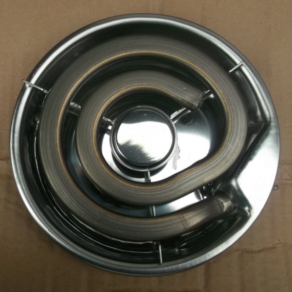
Spiral burners
Visually they are very similar to electric kettle heating element- this is an ordinary heating element, which is designed to heat the installed on it kitchen utensils. Such burners come in single and double types - the second option differs in that the second is located around the first spiral. These devices are adjusted using mechanical rotary switches, where continuous adjustment is used.

Pancake option
Such products have continuous surface, which is heated by two or more heaters mounted on a metal base. Adjustment is made using special switches rotary type, which connect heating elements in various combinations. They have several positions, they are called step power regulators - this is how they differ from previous devices for adjusting spiral burners.
To protect products of spiral and pancake type burners, the developers came up with an original device that automatically turns off the heating element if the temperature of the pan has reached such a value that its contents can splash out and flood the surface of the burner.

Halogen type
Heating elements of various configurations are placed under the glass-ceramic hob in any order, as the designers come up with. The dishes are heated by a special halogen emitter: The area indicated by the LED indicator heats up in a few seconds. On such a burner it is good to cook food without prolonged simmering, and energy consumption is no more than 2 kilowatts per hour.
This option requires cookware made of cast iron or steel - this should be taken into account by all users when purchasing such a stove.
Heating adjustment is carried out directly on the top of the hob using touch buttons, lower cost models include standard control using controls located on the front control panel.

Ceramic devices
This type of heating element is similar to a labyrinth in which spiral from nichrome thread - the design of each burner is thought out perfectly so that the spiral heats maximum area. These products are mounted directly under glass-ceramic surfaces panels where food is prepared, quite often they are used in combination with a halogen version in one stove. To control the heating of these devices, switches with smooth two-stage adjustment are often used.

Oven
The heat inside the cabinet required for preparing various dishes is generated using a special configuration of heating elements, which are specially manufactured using a special technology for use in electric stove ovens. The amount of heating inside is regulated by a switch located on the control panel - a thermostat. Most ovens equipped with a timer, which not only disables the device in right time, but can also be enabled if the user installs the necessary program in advance.
Some models have - a fan distributes hot air evenly throughout the entire volume of the cabinet, so there is no need to turn, for example, a duck carcass while baking it on a baking sheet.
In the most advanced models, a special coating is applied to the entire surface of the oven. high quality enamel coating, thanks to which maintaining internal cleanliness is quite simple. For example, the Hans brand has a special mode - when turned on, all dripping fat instantly turns into ash.

How does the grill work?
In every modern electric stove There is a device called a grill. To implement this function use several heating elements, the action of which is aimed at ensuring that baking proceeds evenly in different modes. The adjustment is made by a combined mechanical type regulator located on the control panel.
Electric stoves are considered not only a unique product for high-quality cooking - they can become a highlight of the design of your kitchen interior. Each buyer will find his own model, made in classic or modern style- variety of sizes and color solutions, availability large quantity functional features allows according to personal priorities.


